Nissan 350Z LS1/TH400 Build Ver.3.1

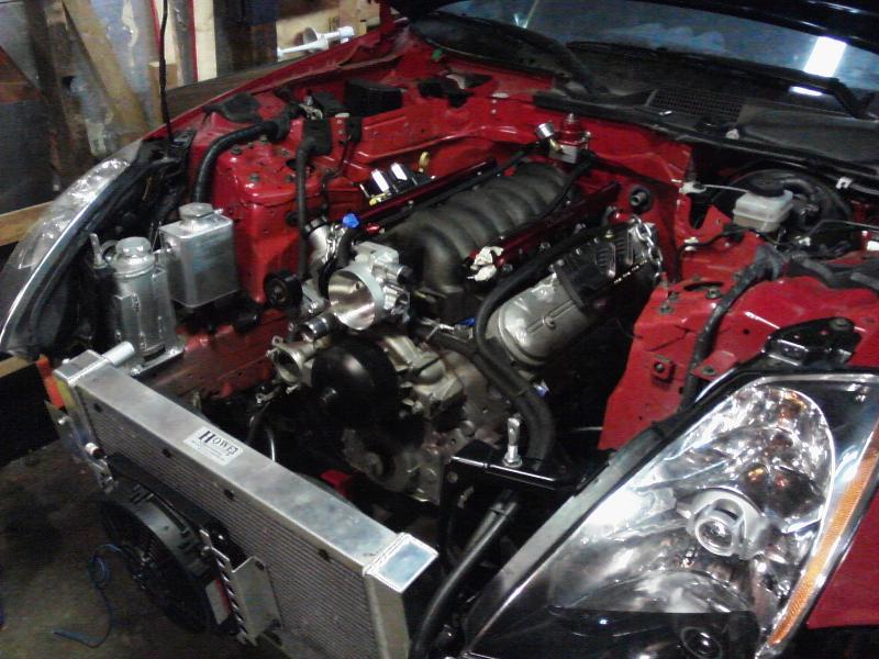
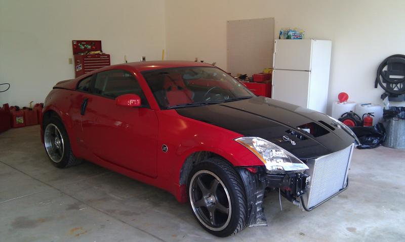
As many of you may know, I have been working on swapping an LS1/TH400 into my Z. I figure it is time to start a thread as I approach completion of the project in the next couple weeks.
To start I want to say that I cannot tell anyone how much this swap cost. I did 100% of the custom work myself and used parts that may not be the same as someone considering this swap would want. I also choose the LS1 because I was able to find one I was comfortable purchasing. I also choose the Th400 over the six speed for ease of installation and I because I live near a drag strip.
Parts Breakdown:
1) 2001 5.7L LS1
2) TCI Built TH400 w/Valve Body
3) TCI Torque Converter w/3600 rpm Stall
4) TCI Flexplate
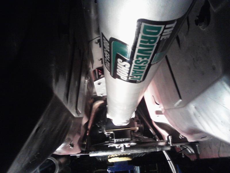
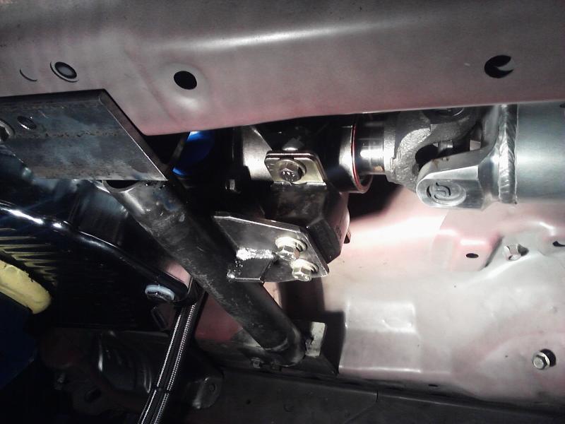
5) Driveshaft Shop Custom Driveshaft
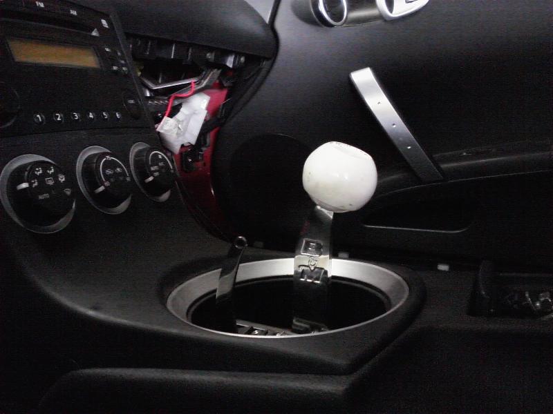
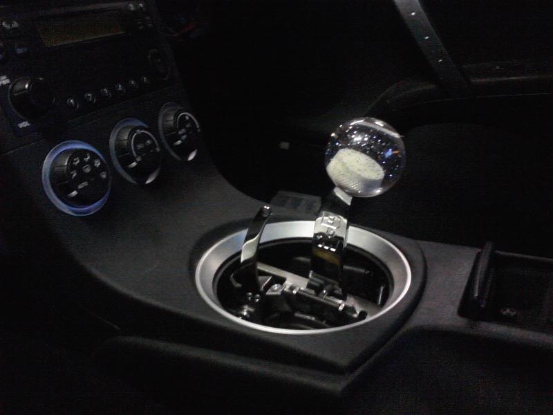
6) B&M Pro Ratchet Shifter
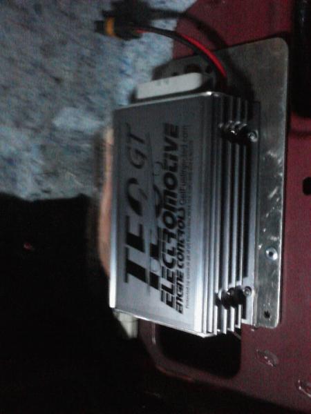
7) Electromotive TEC GT Standalone ECM
8) Electromotive Standalone Direct Fire Ignition Units
9) Derale Transmission Cooler
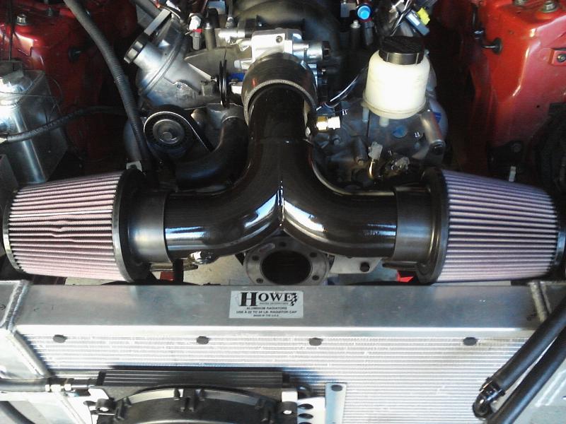
10) Howe Custom Double Pass Radiator
11) Summit Racing Crank Dampner
12) Moroso Coolant Expansion Tank
13) Canton Modified Oil Pan
14) Jantzer Performance Throttle Body
15) FAST fuel rails
16) Speedhut Tachometer
17) 350z Factory Alternator/Power Steering Pump/Sensors
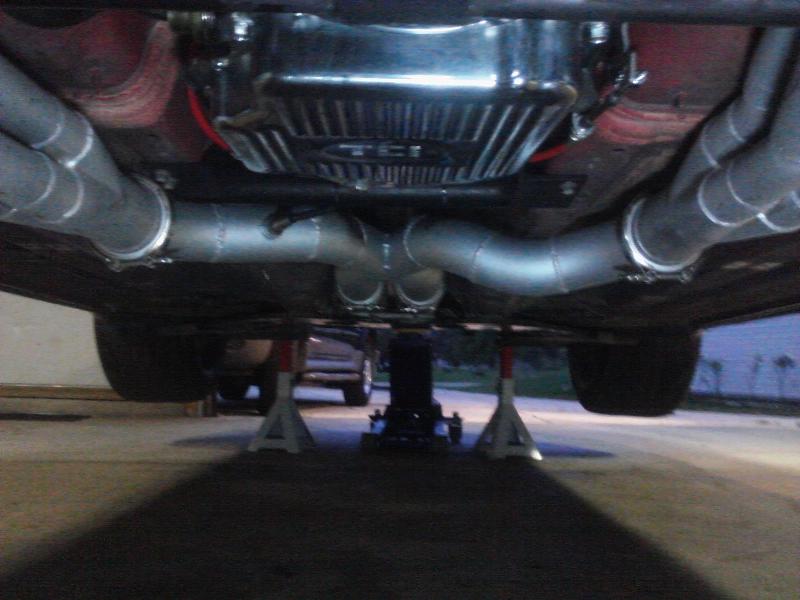
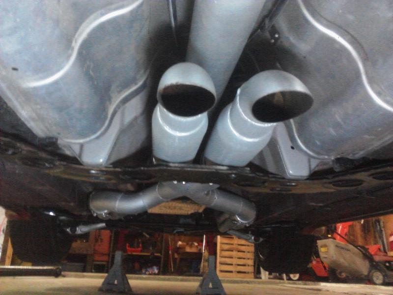
18) Summit X-Pipe
19) Moroso Spiral Flow Mufflers
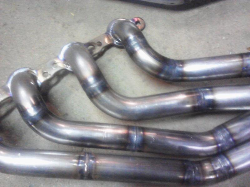
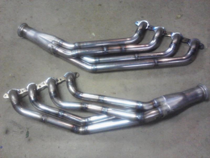
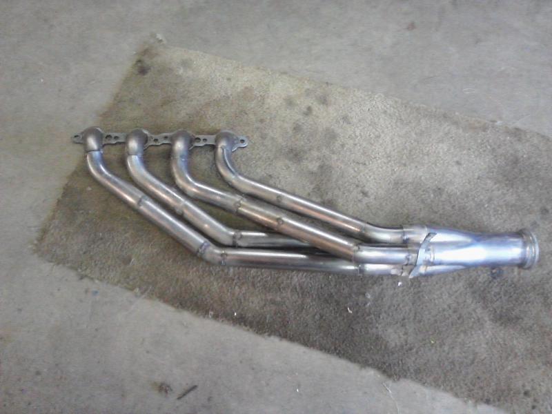
20) Custom Headers
21) Magnecor Ignition Wires
As of right now I am not doing any internal to the motor. Over winter I am looking to do a cam and an intake manifold. Now on to pictures!
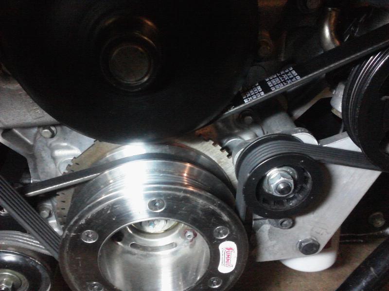
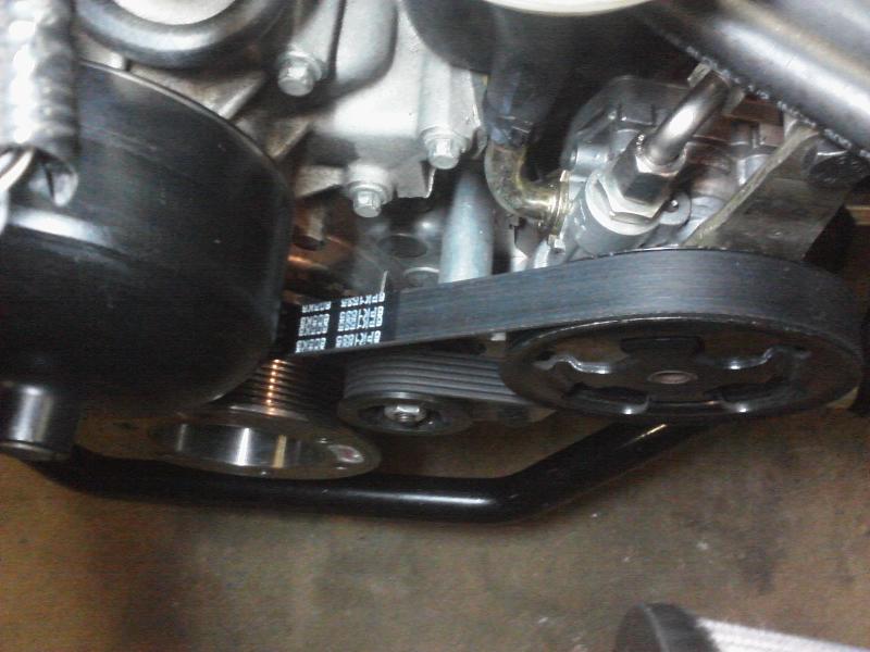
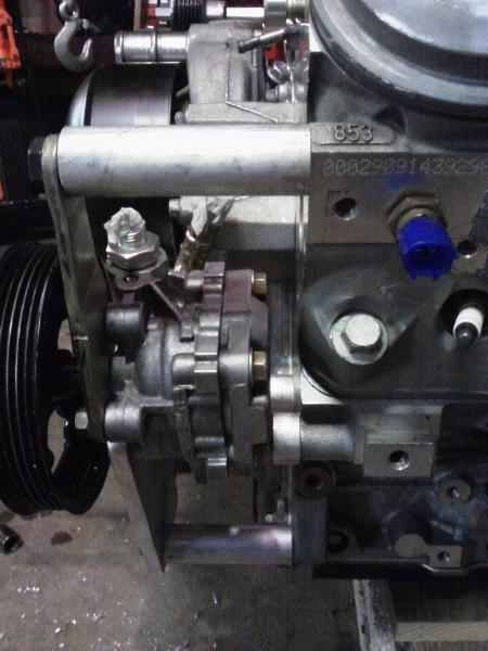
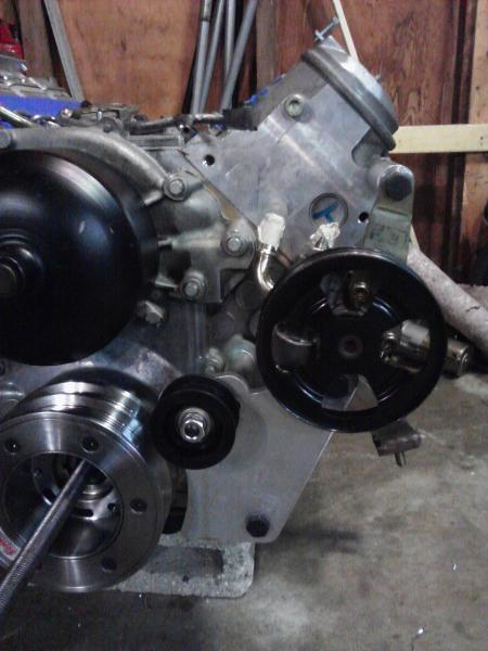
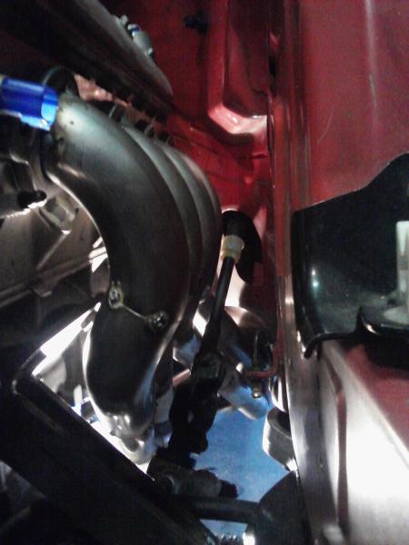
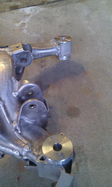
The top gold portion of the bracket is the stock Z bracket pounded flat 
On the back side of this bracket will be the crank angle sensor that reads off the 60-2 tooth gear on the back side of the crank pulley.
Also note that the stock 350z coolant sensor is the exact same thread size as the GM coolant sensor. That nice little sensor with the blue plug is actually the factory Nissan sensor so my gauge still works.
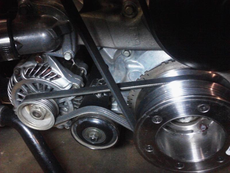
Small update today. Finished my power steering pump/crank angle sensor bracket!
Going to finish up my intake, wiring and exhaust this weekend! Then it is time to start her up! Hoping for Sunday to be the day!
Made some really good progress. Just finishing up the wiring and some of the small things like flushing lines and tightening bolts. Then it is time to start her up! Aiming for Saturday!
New Headers
Passenger side header is complete!
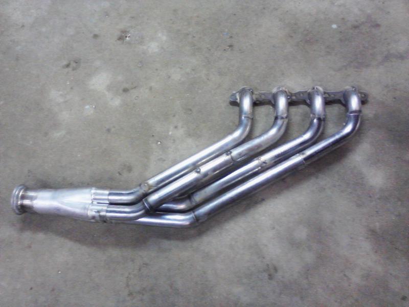
Driver side header is completely tacked together and ready for weld!
Still putting interior panels on and cleaning up small little things here and there.
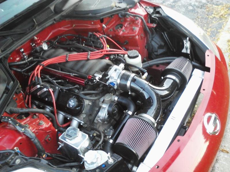
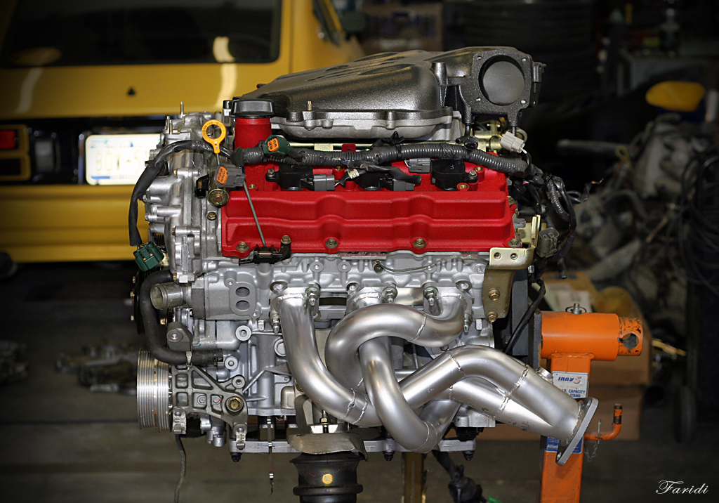
Here are some pictures of how nicely the stock 350z accessories can fit on the LS motor. These are custom brackets I made but they were extremely simple to make and work well!
You can see the 60-2 timing gear on the back of the crank pulley nicely hidden out of sight.
New startup video
[youtube]http://www.youtube.com/watch?v=NQ2KPra6LfE[/youtube]
Still putting interior panels on and cleaning up small little things here and there.
New Video
[youtube]http://www.youtube.com/watch?v=XKH-OgzLGQM[/youtube]
Had a chance to take the Z out for a quick spin last night late at night. The thing is going to be a beast . Hoping to put a good tune in it this week and try getting some in car videos.
Testing the Line Locks
[youtube]http://www.youtube.com/watch?v=Yz1q5-v3a64[/youtube]
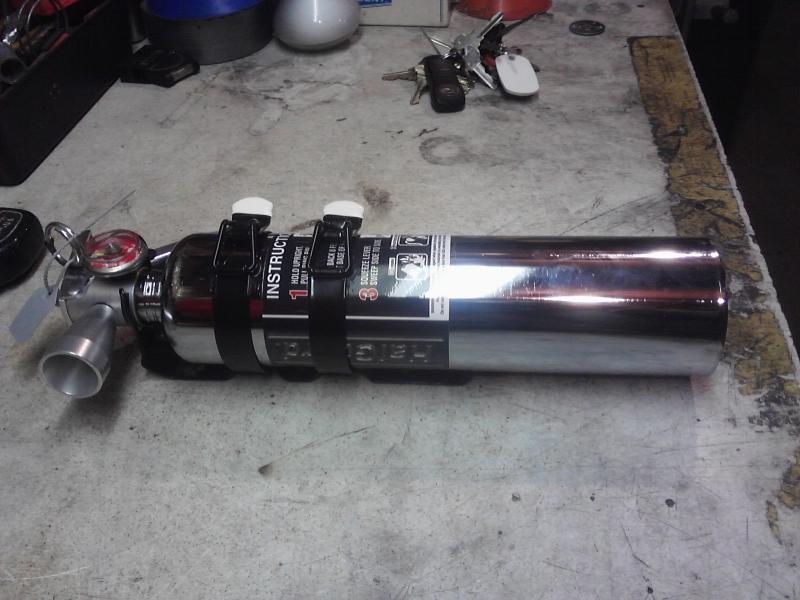
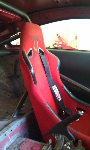
I have some drag slicks and wheels on the way also. Seats and harnesses will be in along with a fuel cell and hopefully a 100-shot of nitrous soon!
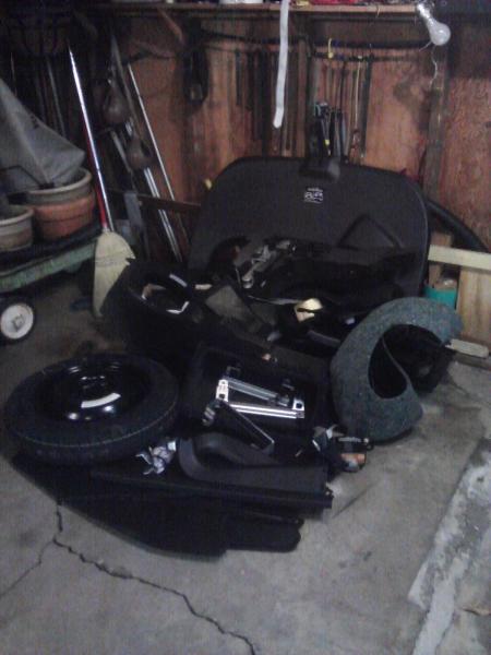
Started the winter drag build V3.1!
Goal is lighten the car and get it under 3000lbs wet without driver. I will also be adding some safety items and things like a differential brace in order to help improve my reliability and times at the track.
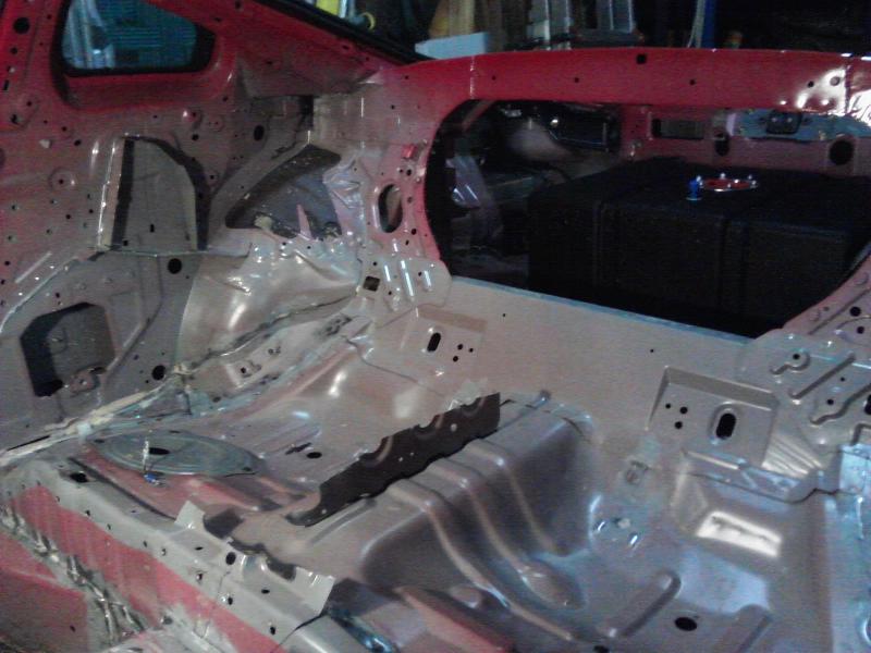
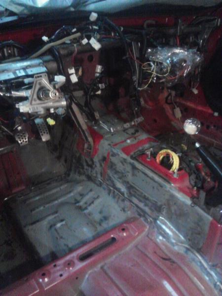
Started in the back half by stripping the interior. Going to start removing the tar and sound deadening this weekend and then move onto under the dash and the front end.
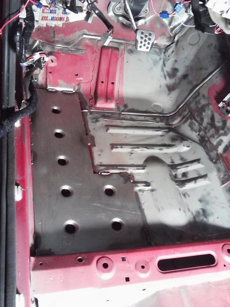
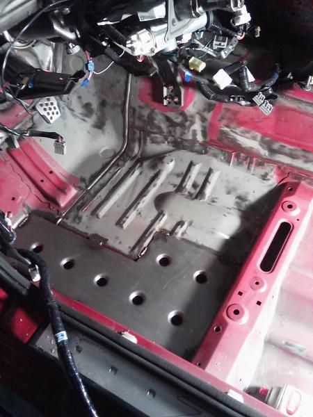
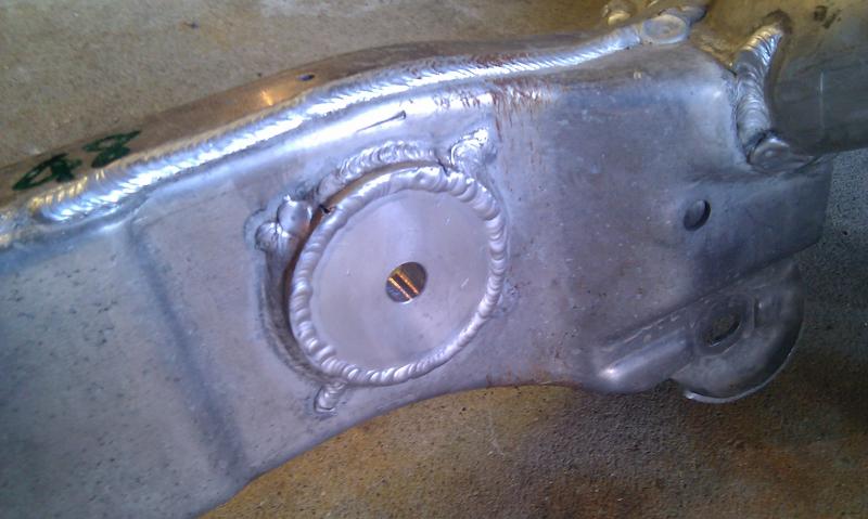
Got the driver side sheet metal filler panel installed. Turned out very nice in my opinion. For anyone who has not taken out their carpet, there is actually a foam filler piece that fills a large void to the inside of the frame rail.
This is the hole that this filler piece is now covering.
Made it from 16ga mild steel on a waterjet. Then made my own dimple die to make the strengthening dimples and add some appeal to the panel. Passenger side should be finished tomorrow.
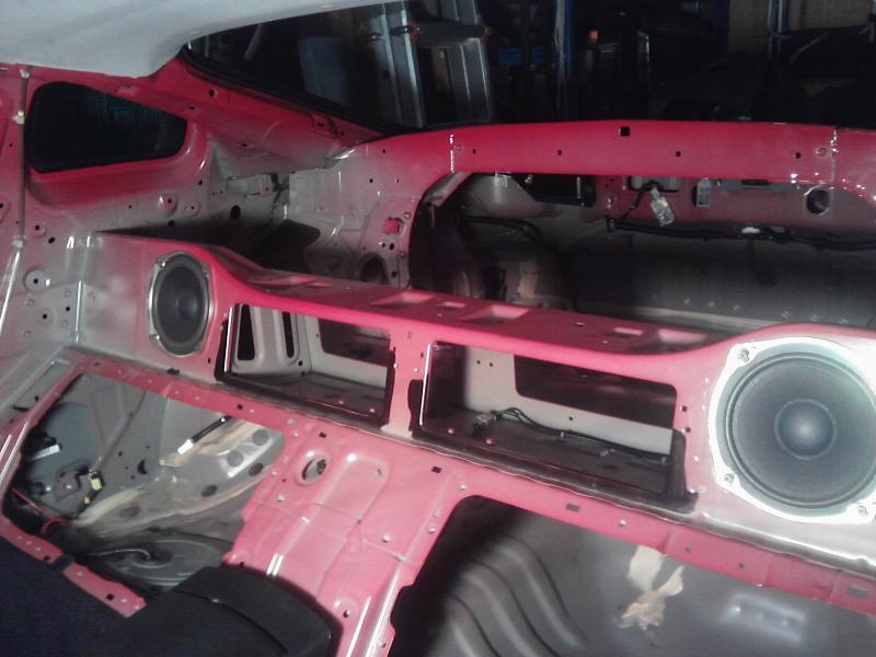
99% of all the sound deadener and tar is removed finally. Just need to finish cutting and grinding where the speaker enclosure was.
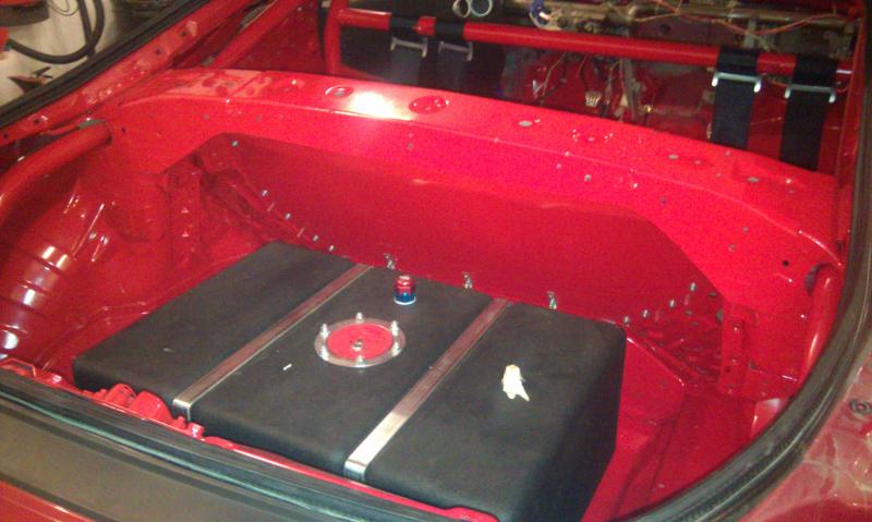
Then it is onto mounting the fire cell and making the NHRA legal fuel cell firewall and welding in some things such as my 4th and 5th mounting points for my harnesses.
Been working daily on the solid bushings for the subframe and differential. Been trying to machine one a day as right now it is not a huge rush until the fuel cell is in.
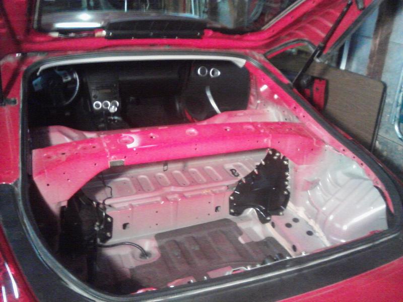
No more speaker enclosure! Just need to fill in the holes and finish removing the parts where it was spot welded to the chassis!
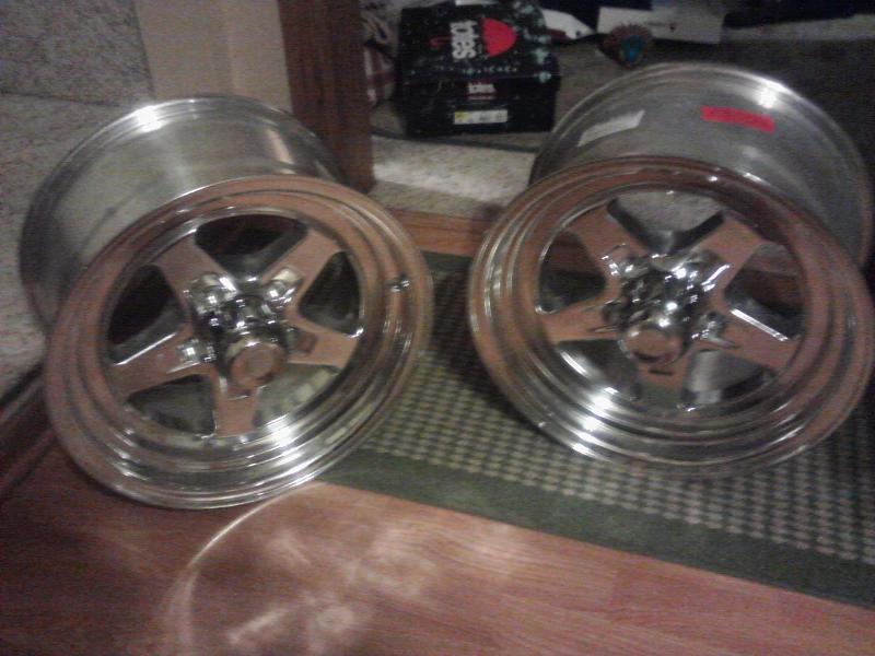
New Wheels
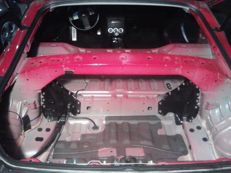
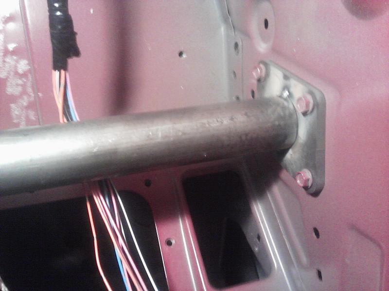
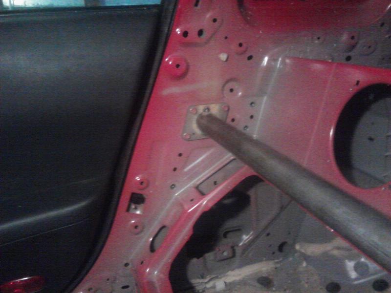
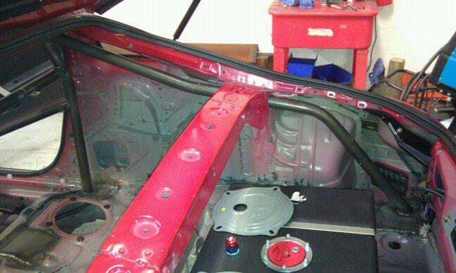
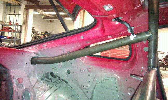
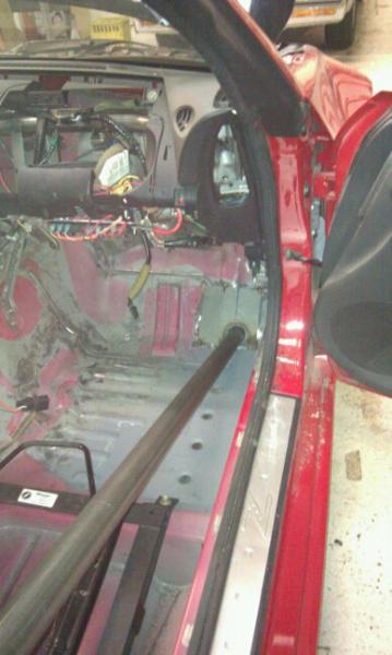
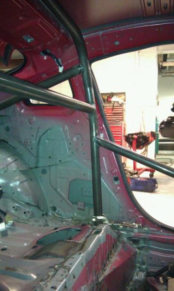
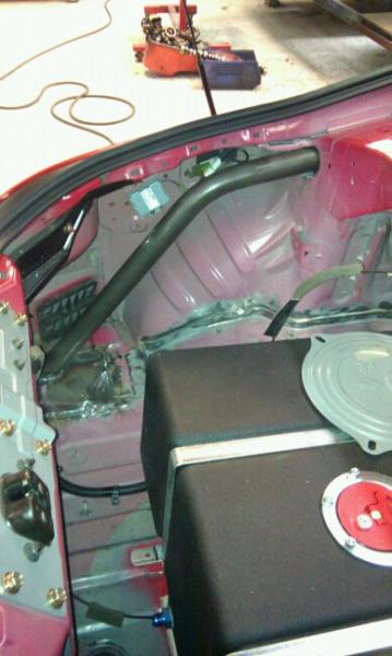
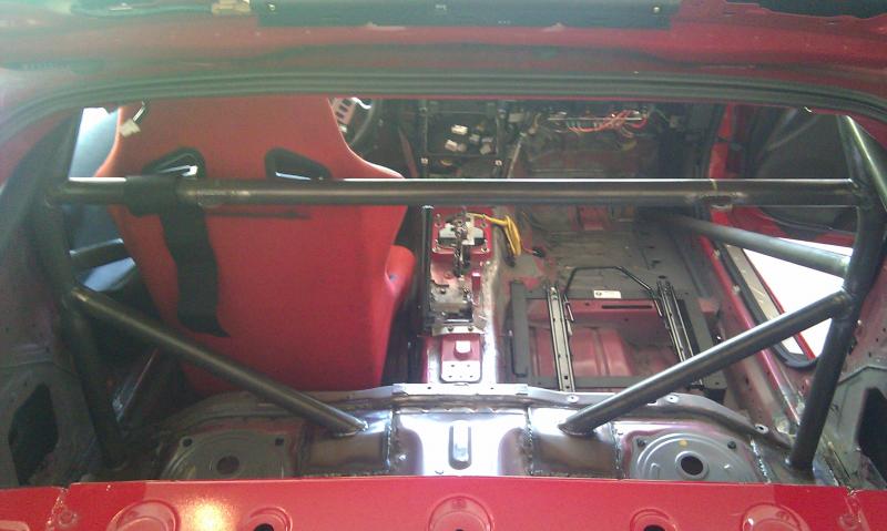
Here is my temporary mid-brace for when I cut out the speaker enclosure. Eventually a cage will be in once I have a better understanding of how deep I want to go racing.
Flanges are waterjet cut 1/4″ plate and the tube is .083 wall 1.5″ diameter tubing.
About 75% done stripping the sound deadener out of the interior. I have a couple spots on the tunnel and behind the dash to finish and then it is all out. Still working on removing all the glue though.
Speaker enclosure should be cut out by next week and all all the glue removed. Then it is on to touching everything up with the sander.
For now I am making a “mid-brace” to help maintain the strength of middle of the car once I cut the speaker enclosure out. I made the brackets yesterday and am picking up the tubing in the morning.
Hope to have the mid brace done tomorrow. Also picking up the material for my solid differential and subframe bushings in the morning.
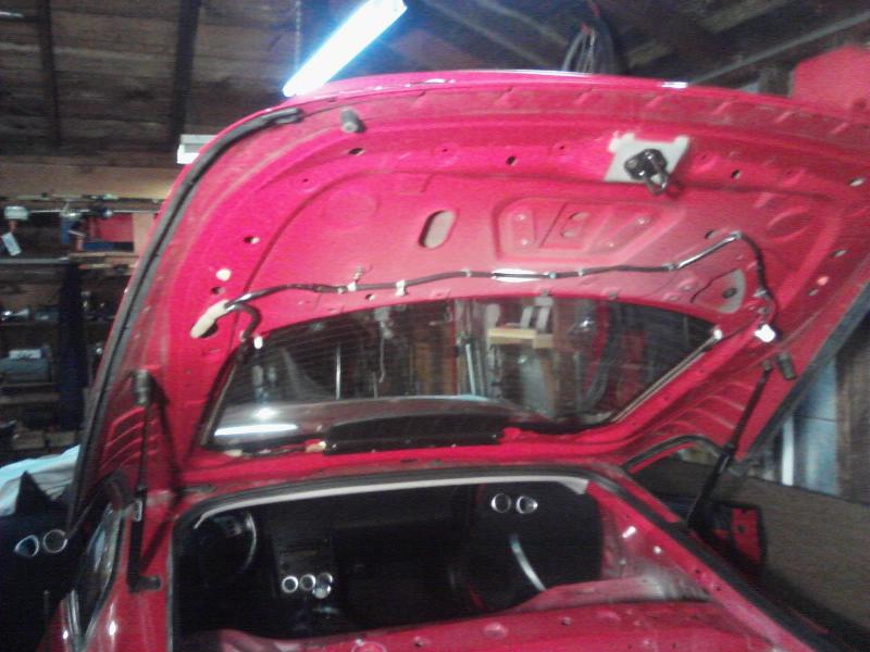
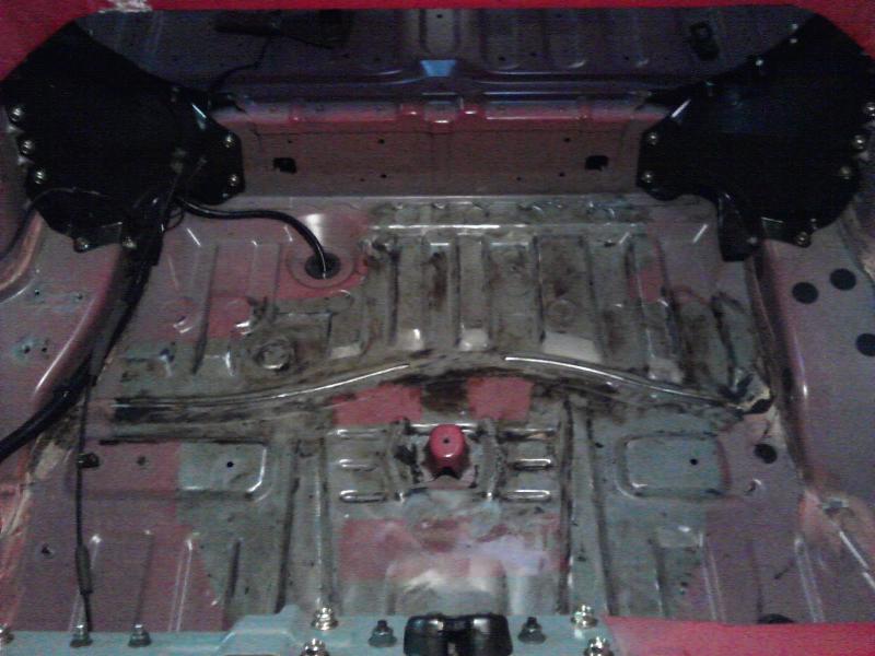
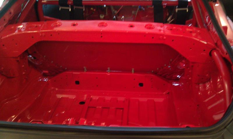
Got the first stage of sound deadener removal completed on the trunk
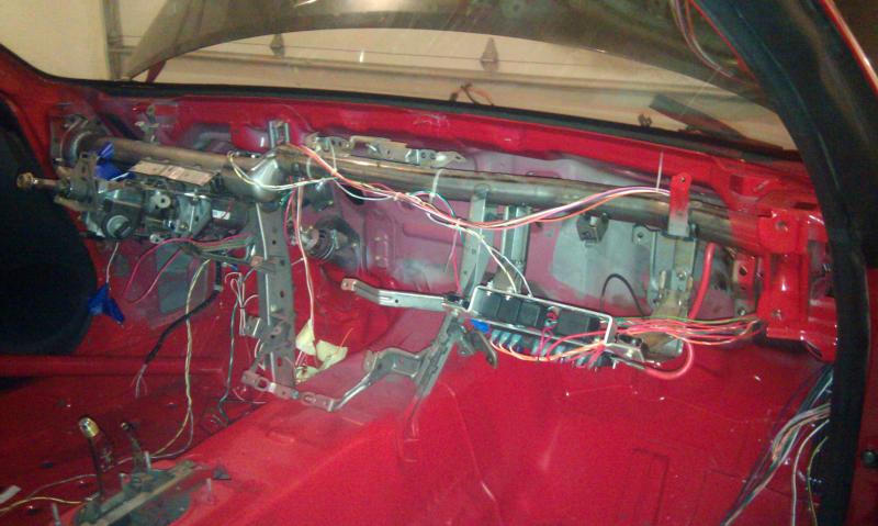
Look at all the sound deadener and crap to remove under that dash!
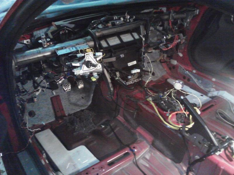
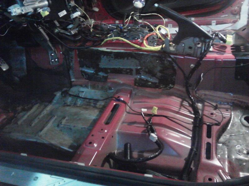
Got a start to removing the sound deadener on the driver side
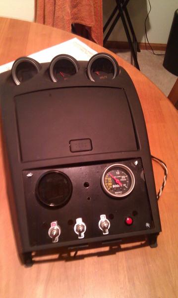
My new gauge and switch panel where the radio was. Air/Fuel gauge and vacuum/boost gauge. The switches are main power relay, data log, nitrous and wideband calibration. Each switch will have an indicator LED by it also which aren’t shown in the picture. There will also be an error code indicator between the gauges. Still have to space the panel out correctly so it sits flush, but you get the concept.
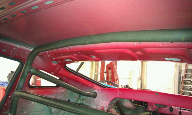
Pictures of the cage that Clocks Off Racing is putting in the Z! Just going with a 10.0 cage for now. Planning for a Ford 8.8 solid axle and adjustable four link suspension this upcoming winter.
Just some pictures from over the last month or two. Have a bunch more updates but I am waiting until they are completely finished to post them.
Welded in solid subframe bushings
Pictures of the finished cage also.
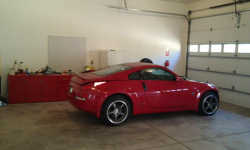
So I finally moved into my new house this week and the Z got delivered! Sitting in her new home with the new larger Howe radiator and and Clocks Off Racing tubular radiator mount.

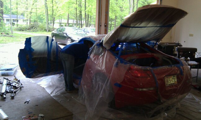
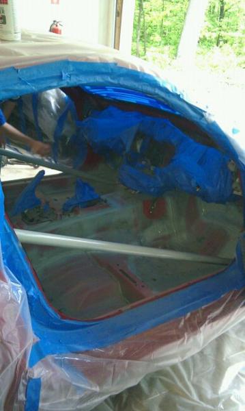
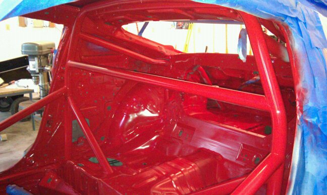
Well the cage and interior has the first coat of paint on in it. Going to finish painting today! It sure is red but there wasn’t much else I could do.
I did want to share some pointers for anyone that is considering this swap or in the process of swapping an LS motor in their Z.
First, be realistic with your budget and goals. As far as budget goes, expect to spend more than anticipated. However there are some things you can do to really bring the price down if you are realistic with your goals. This first is outline the power you really want. There is always talk about what LS motor to swap into the car and which is better. Obviously more displacement is better. However, if you are aiming for something modest like 500whp, even 5.7L can make that power with ease, especially when boosted. I saved enough money purchasing the LS1 instead of an LS2 that I could easily build the motor with the money I saved. This can be a huge deal on meeting you budget and planning for future improvements.
Second, Don’t ever sand down the ignition mounting bosses on the valve covers if you don’t use the stock GM ignition coils… They are crappy castings full of porosity  . If you grind out the porosity and weld it up, more just comes through.
Third, the switch to cable throttle is easy to do as long as you have a cutoff wheel and a small welder. I will try to post some pictures but it was quite straight forward. On the accelerator pedal you can simply remove the pedal position sensor unit and bracket. I just welded a simple piece of u-channel steel to the upper portion of the rod to attach my throttle cable to. Works awesome! The stock Z pedal has between 1/2″ and 5/8″ to little travel for the LS throttle cam so you won’t be able to get 100% throttle. On the back side of the pedal there is a bump stock that hits the floor limiting travel. There is actually two ways to take car of this. One way is that you can get a smaller radius throttle cam. The second way, which is how I did, is to cut a 1/2″ out of the bump stop so the pedal travels further. This does mean the throttle goes further than normal. If you don’t like this and would like it to be closer to the stock pedal height at 100%, you can get about a 1/4″ of travel by putting spacers between the firewall and the pedal mount. Unfortunately, the the studs on the firewall will not allow for 1/2″ spacers. This would be a compromise as you would still have to cut a 1/4″ from the stop. Using a smaller radius throttle cam will maintain the stock pedal height at 100% throttle. If you use an electronic throttle body for the LS motor, you should just swap out the pedal assembly from one of the cars that the motor came in.
Forth, be prepared for you car to handle different. My car seems to be almost normal, but my motor is lower and further back than most of the kits out there. You are putting a heavier motor in the car so be prepared.
Lastly, try to retrofit sensors from the stock Z to the LS1 motor rather than trying to make the two ECU’s communicate together. I have heard horror stories about the companies that try to flash everything and make the stock guages work. The stock Z coolant sensor is the same size as the LS one. You do need both though as the stock Z sensor is only for the gauge while the Gm one will be for engine control. Both are important. The oil pressure sensor from the Z can be easily retrofitted to the LS motors. Any hydraulic fitting company will have a port plug of the correct size which can be drilled out and tapped with the 1/8 BSP that the stock sensor requires. For tachometer, you are best off buying a speedhut tach and installing it in your cluster. It will look near stock and work great! Both the needle and digital speedometers will work. The odometer and trip meter will also work.
Well… ALL of the stock wiring, control modules, relays and fuses have been removed. In the process of rewiring things like the iginition key, power windows, taillights, headlights and wipers back in.
Finished labeling all the pigtail wires left on the connectors that go to the headlights and tailights along with the pins on the combination switch on the steering column. Just have mount the relays now and run the wires.
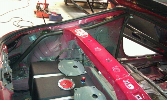
Also 90% finished with my regulation firewall for the fuel cell. Just need to make a small lip on the top of the strut bar that goes up to the hatch glass.


The pictures and progress of your 350z build is very impressive.
I would like to build a 350z like yours.
I see that you built your own transmission mount.
Are engine mounts of your own creation? If so would you please
enlighten me on the dimensions.
You mention rewiring of the electrical circuits, were there any problems or was it fairly straight forward?
Last but not least the custom headers.Are they a kit that you can piece together?
I look forward to seeing more pictures and progress of your 350Z.
Thanks for your help.
Paul Meger
If you are giving out mount dimensions include me! lol