Big Boost’s VR6 Audi S4 BAT Build!

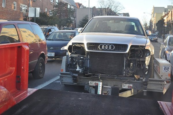
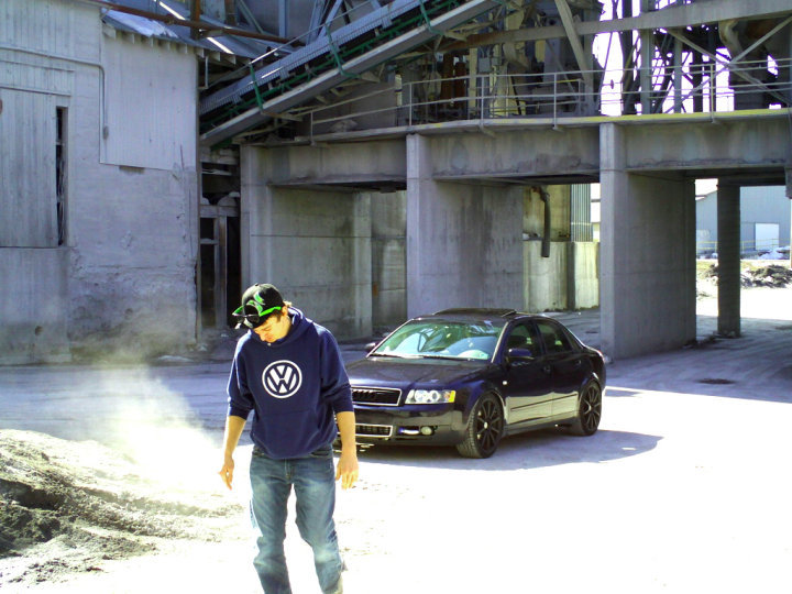
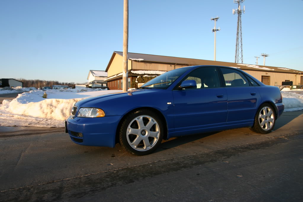 The short story. 2008. Stage 3. VAST. Prince. Mike. Michigan. Neil. Milwaukee. Awesome. Misfires. WTF! CEL? WTF? New program. Cool. Misfires!! Help! Again. Neil. Cool! Loving. Life. Summer. Base file. 12.2@116mph. VAST! 2009. Winter. Hit. Pot hole. Shit. Totaled! Sell parts. Prince. “Dude…Race Car!” Me. “Hey honey, do you care if I build a race car AGAIN? It won’t cost THAT much?!” Wife. Says. Yes. America! FUCK. YEAH! 034. Javad. Issam. Dan. VR6! Conversion? What!?! Damn. I. Need. That. Shit. In. My. Life. Must. Pull. Engine. And. Trans. Leng! Keng! Two brothers. Milwaukee. Hell. YEAH. Transmission. Rebuild. Local. Ben. Import Automart! Fabrication? Local? Jon. Best friend. Yes! Waiting. On. Parts. Took. Forever. 2010. Here. It. Is.
Build Sheet Info:ENGINE
AAA 12V VR6 OBD2
JE FORGED PISTONS 9:1 COMPRESSION 82MM – POLISHED TO REDUCE SURFACE AREA AND CARBON BUILD UP
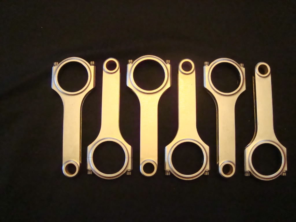
EUROSPEC FORGED H-BEAM RODS WITH ARP ROD BOLTS
ENGINE BLOCK OVERBORED BY 1MM (2.9L) OEM MAIN BEARINGS
BALANCED ASSEMBLY
POLISHED CRANKSHAFT JOURNALS
JOURNALS LINE HONED
OEM MAIN BEARINGS
ARP MAIN STUDS
ARP HEAD STUDS
MLS HEAD GASKET
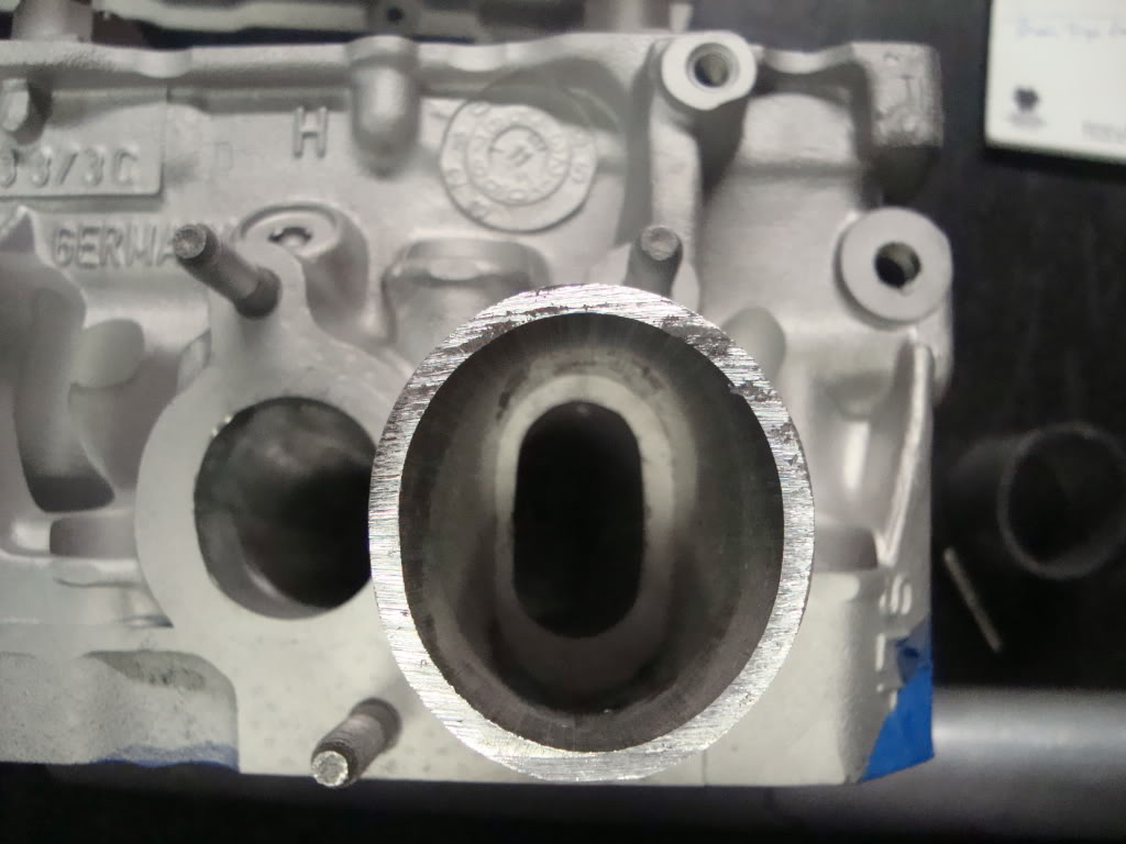
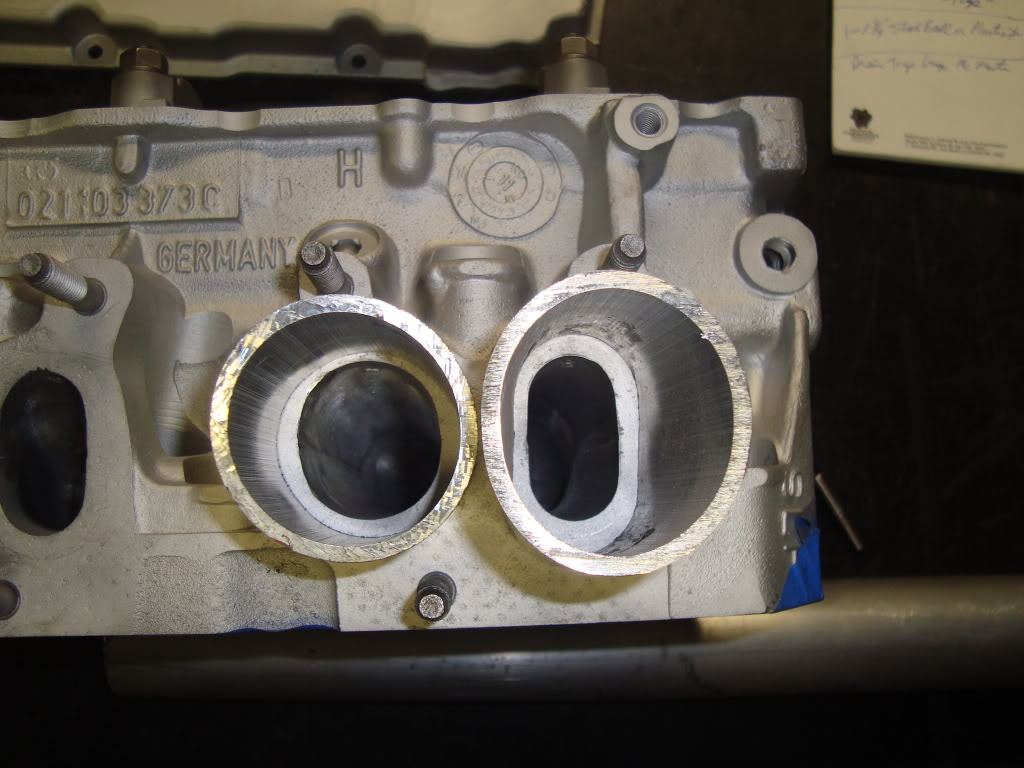
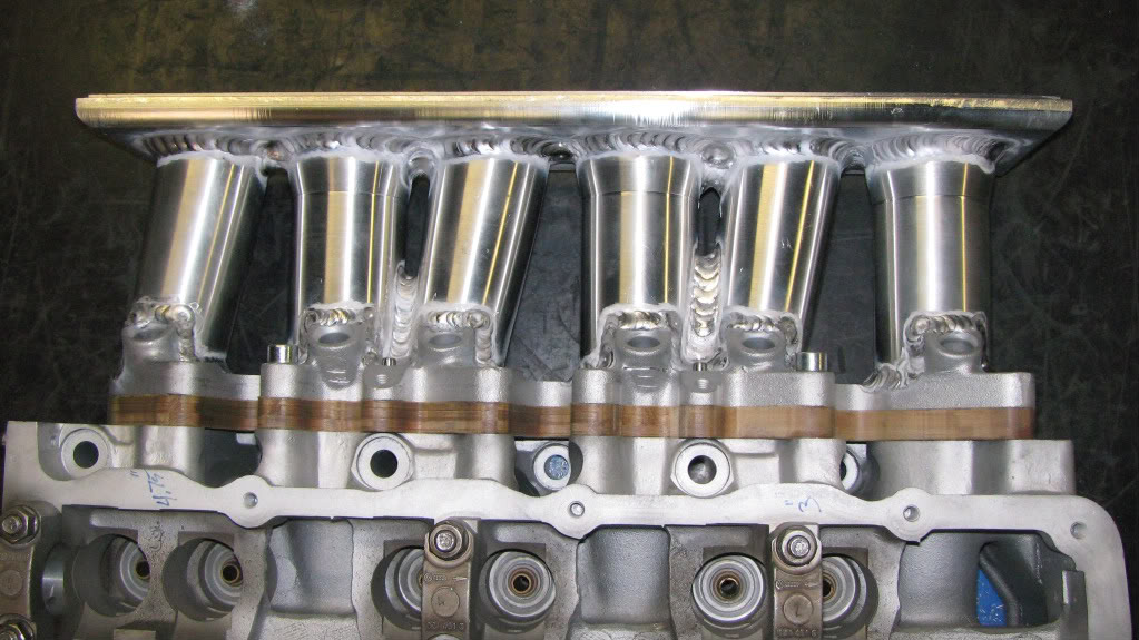
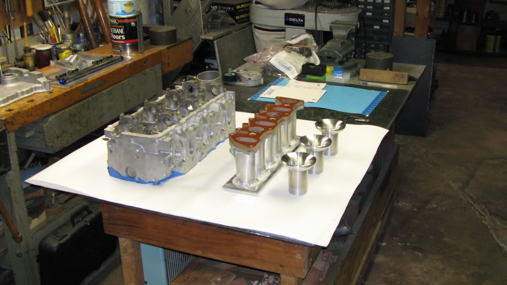
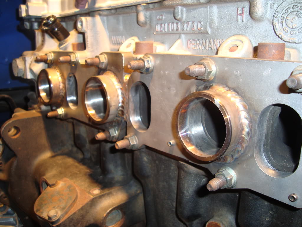
02 INDUCTION STAGE 3 PORTED AND POLISHED CYLINDER HEAD WITH MATCHED INTAKE RUNNERS AND PORTED AND POLISHED EXHAUST RUNNERS
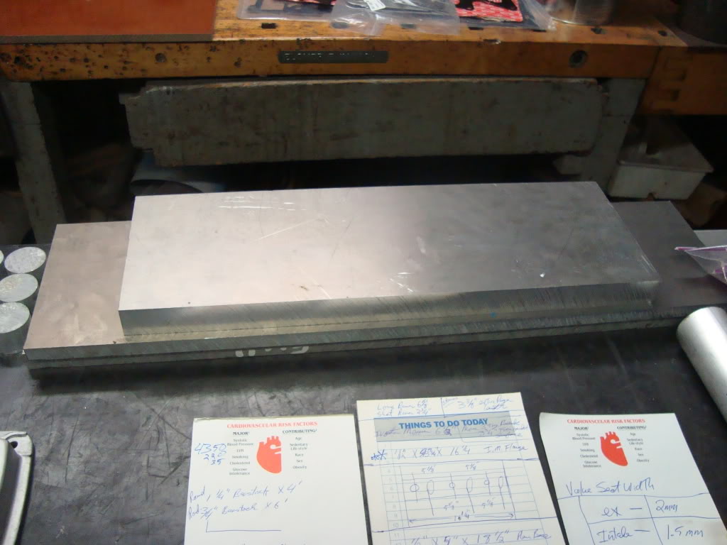
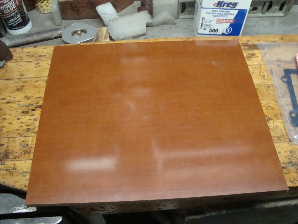
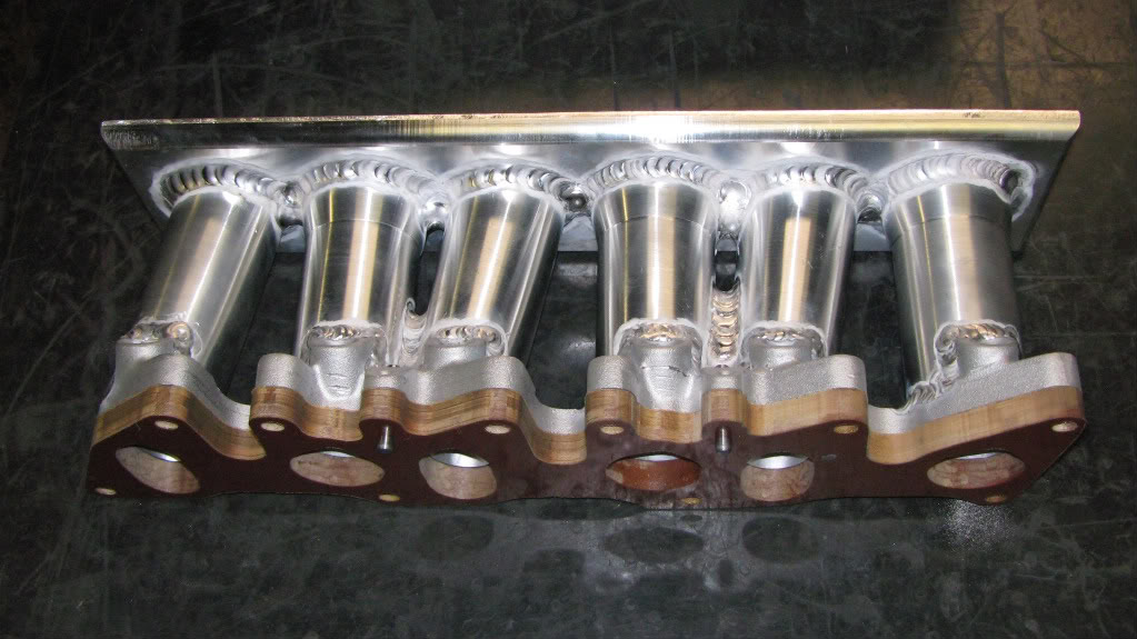
1/2″ PHENOLIC SPACER WITH DOWEL PINS – PERFECTLY ALIGNED TO INTAKE AND FACE OF CYLINDER HEAD – TOTALLY SMOOTH!
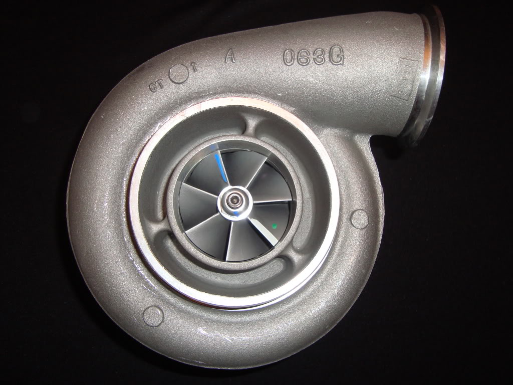
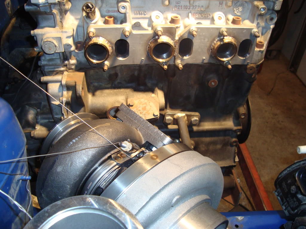
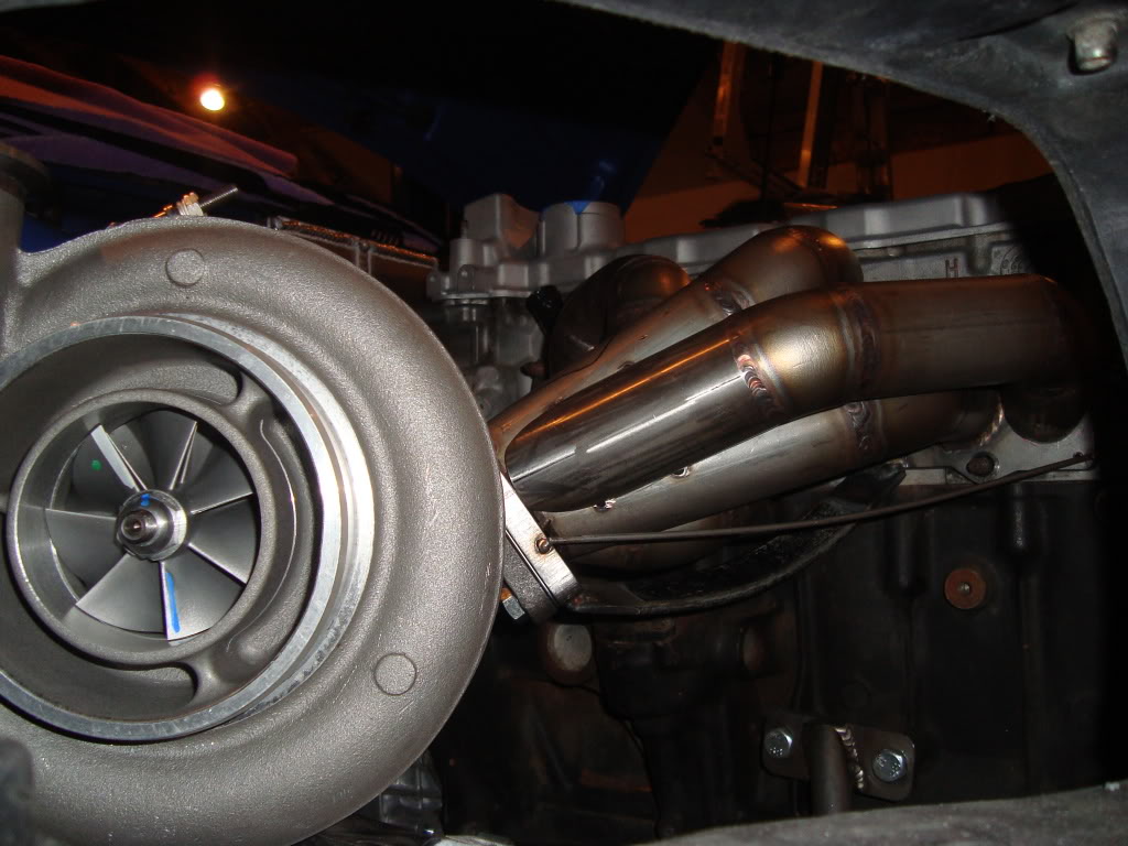
BORG WARNER S400SX3 TWIN SCROLL T4 TURBO 101MM EXDUCER
TWIN TIAL 38MM BILLET WASTEGATES WITH ATMOSPHERIC DUMPS
TIAL 50MM BILLET BLOW OFF VALVE WITH STAINLESS FLANGE
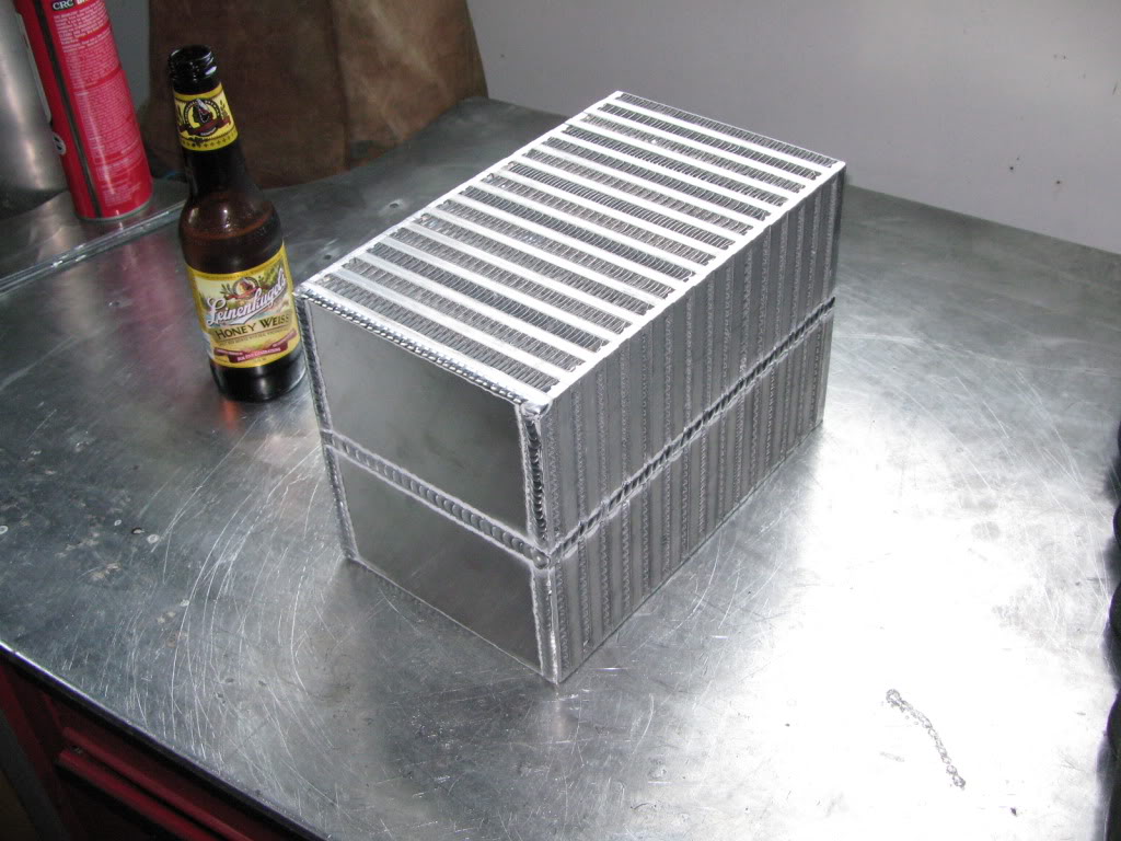
AIR TO WATER INTERCOOLER
CORE SIZE 11X7X6.5 (500.5 CUBIC INCHES)
FULL SIZE HEAT EXCHANGER
SPEARCO WATER PUMP
3” ALUMINUM INTERCOOLER TUBE
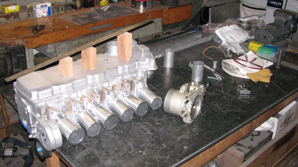
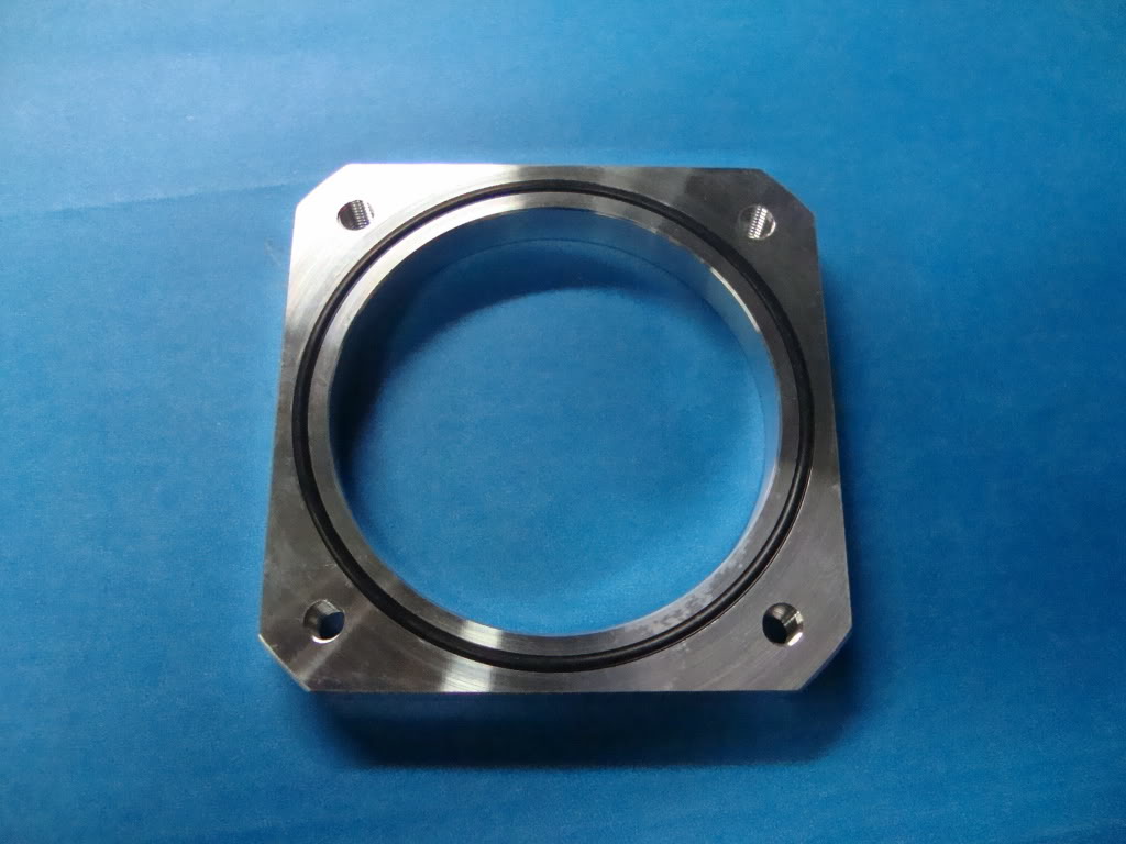
80MM NISSAN Q45 THROTTLE BODY (MODIFIED)
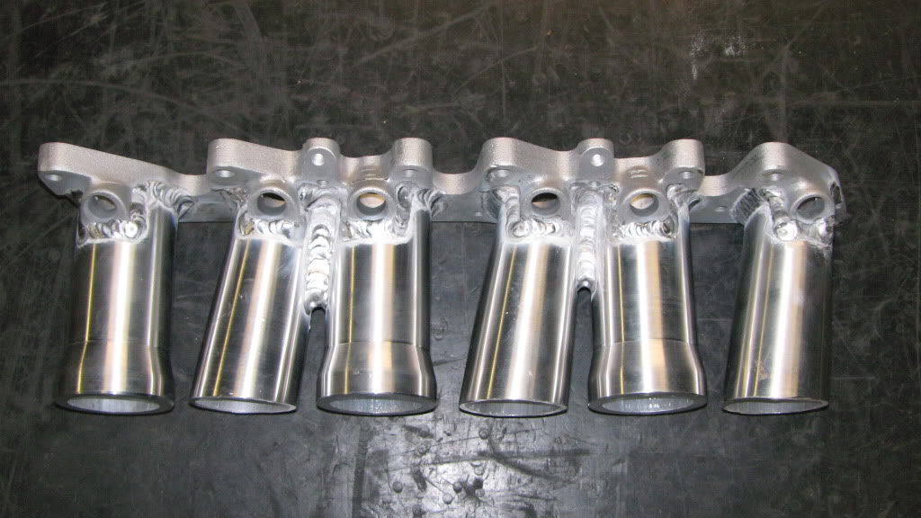
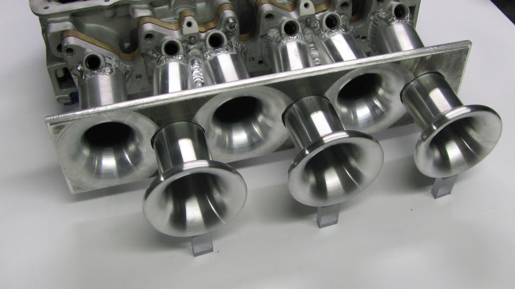
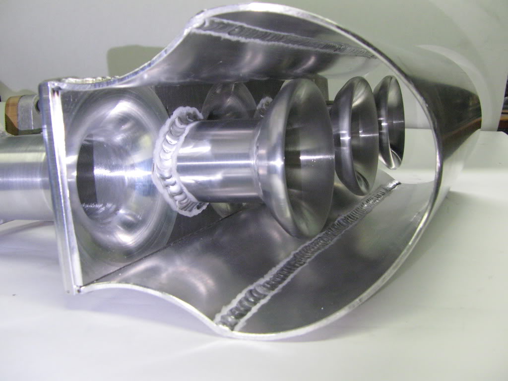
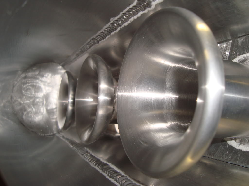
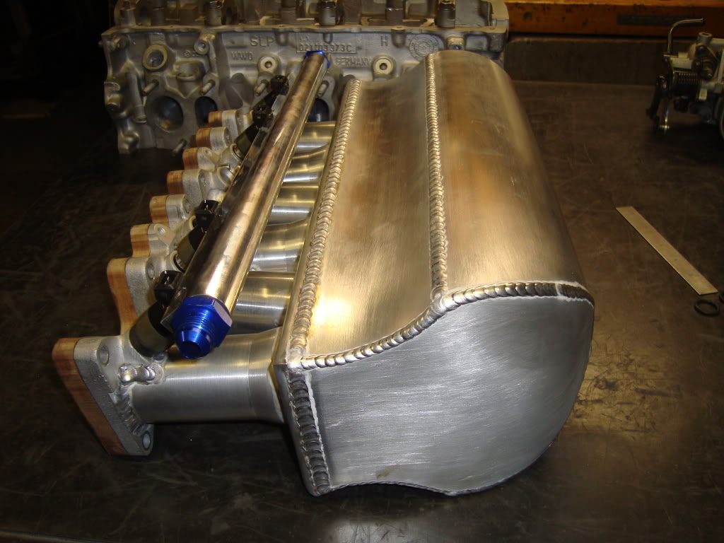
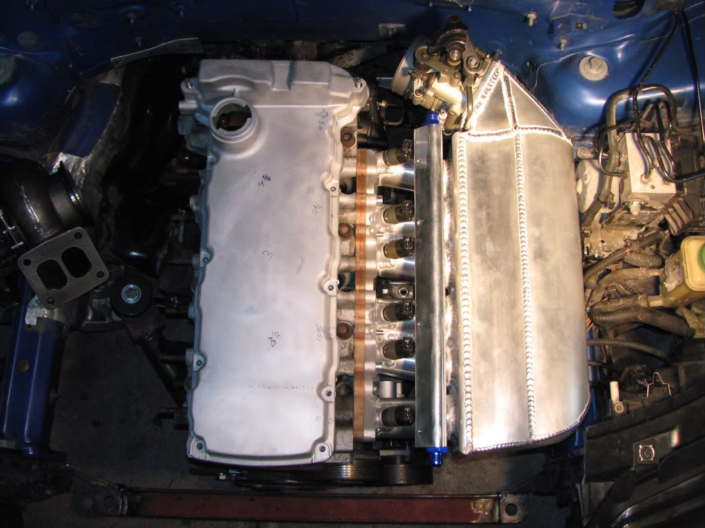
02 INDUCTION EQUAL LENGTH ALUMINUM BIG PLENUM INTAKE MANIFOLD
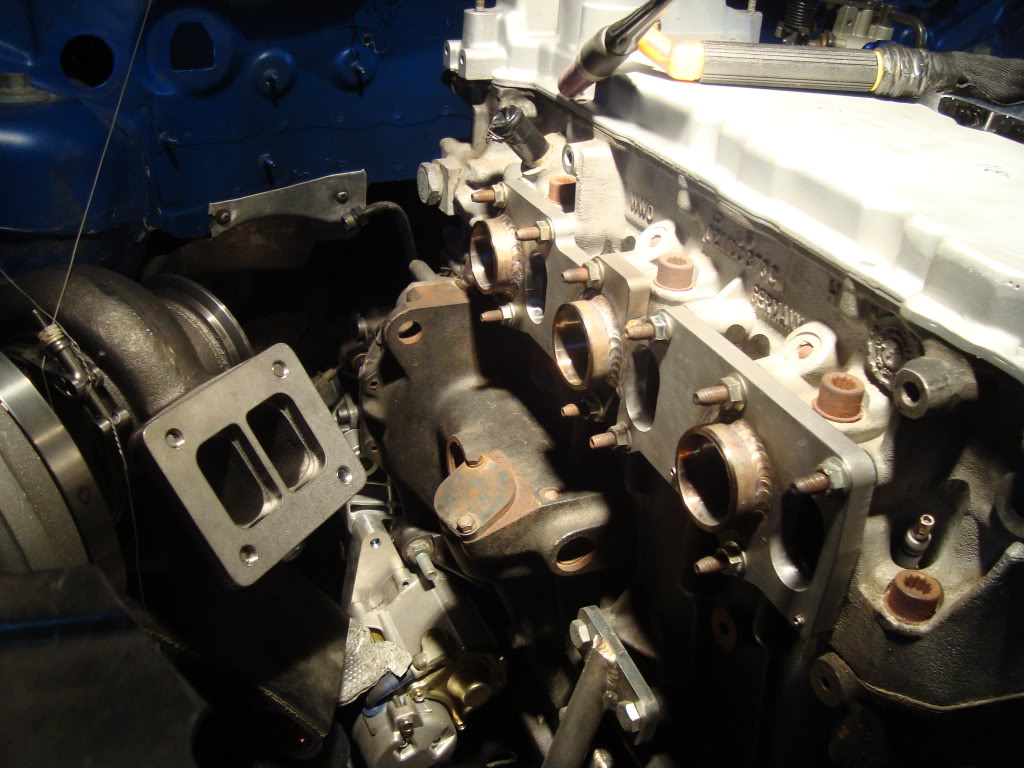
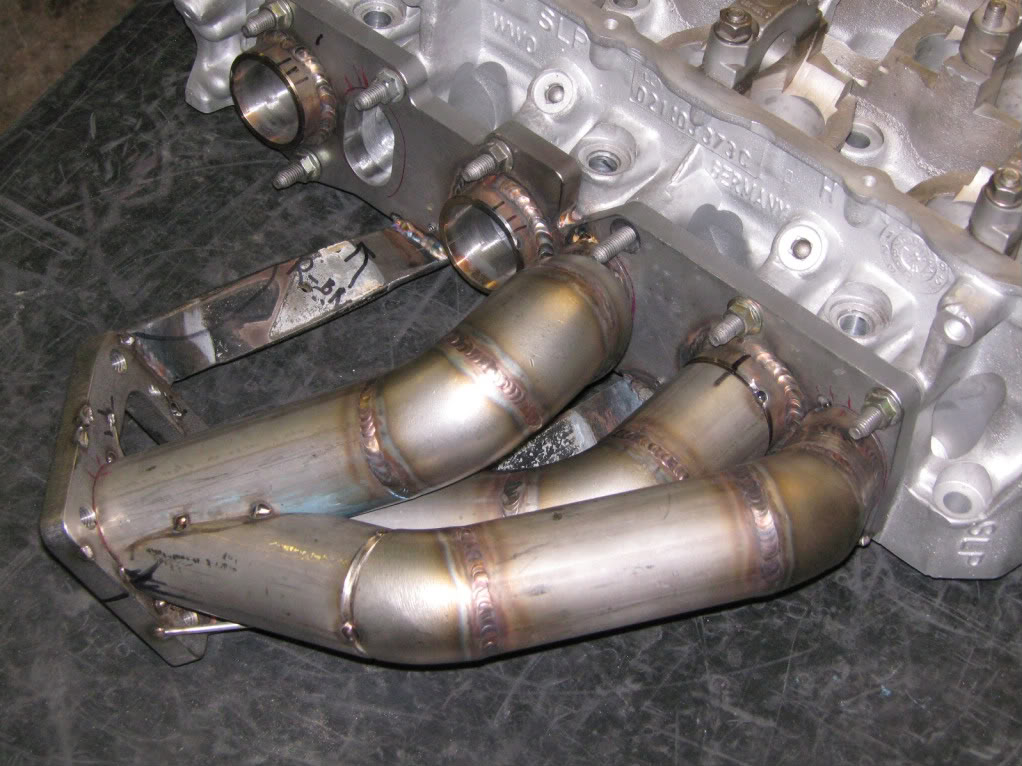
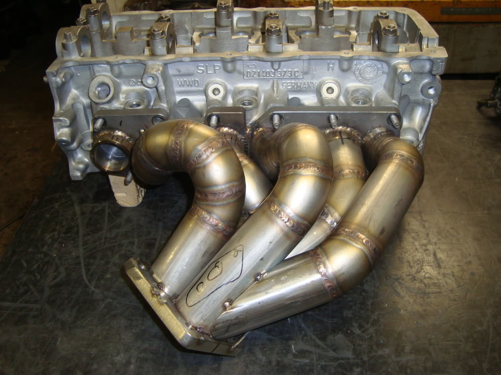
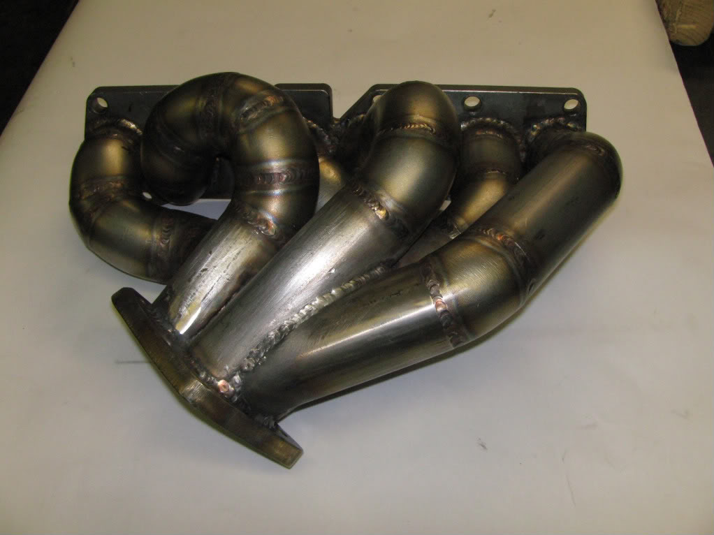
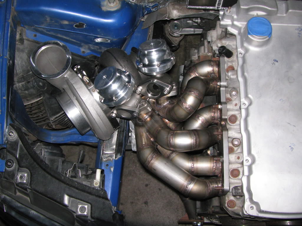
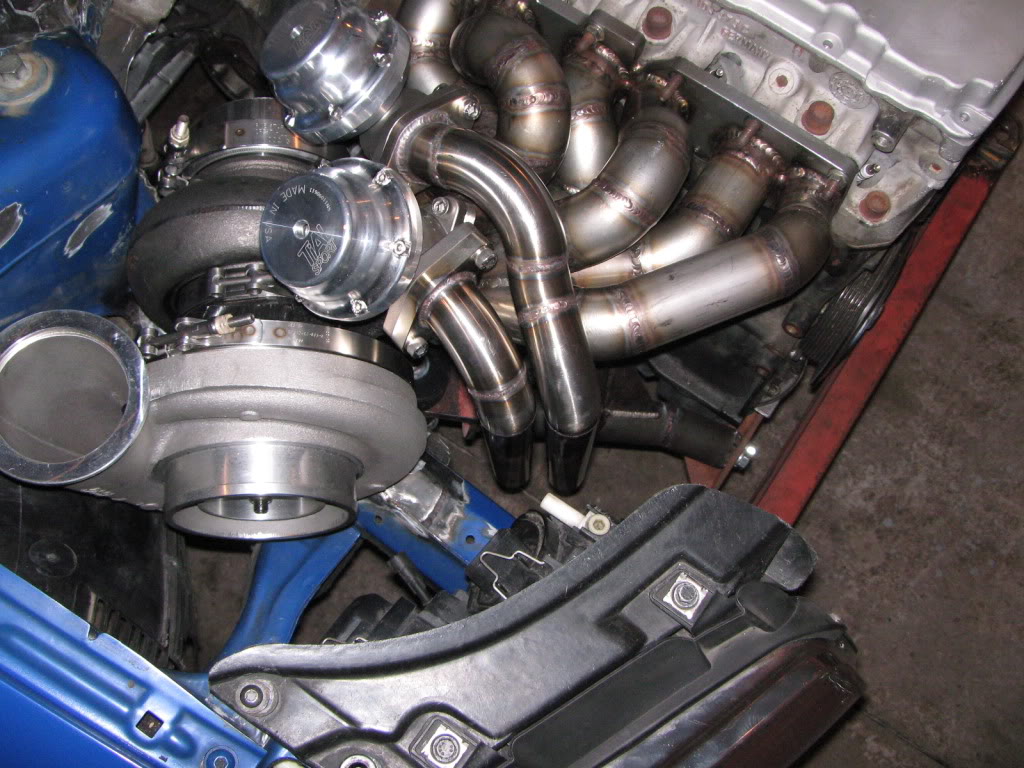
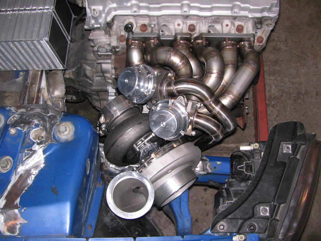
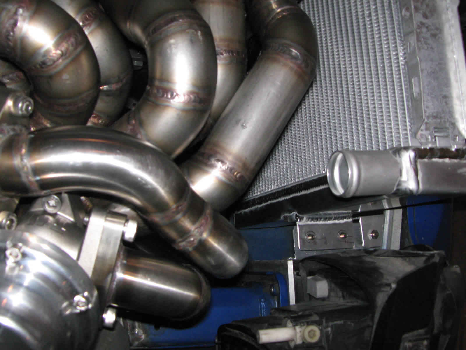
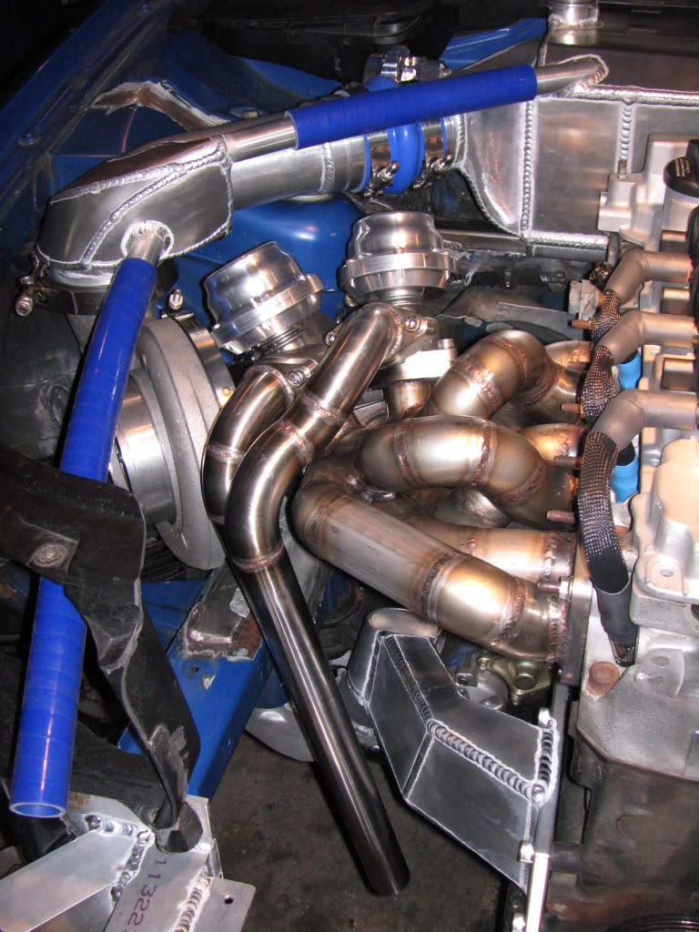
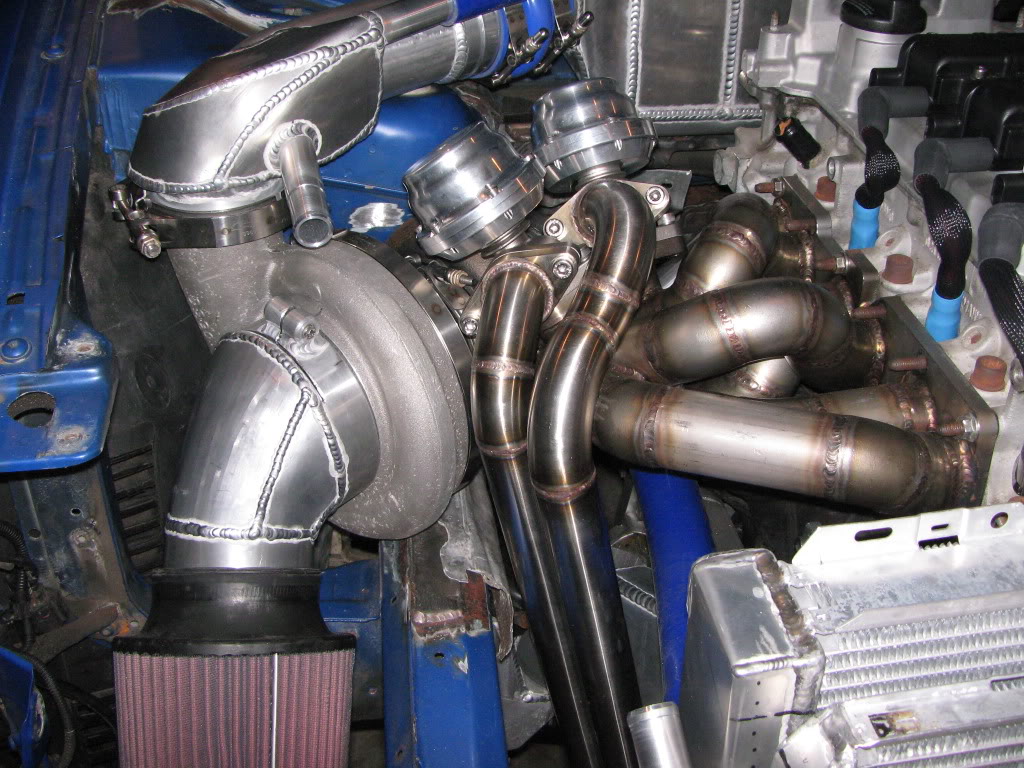
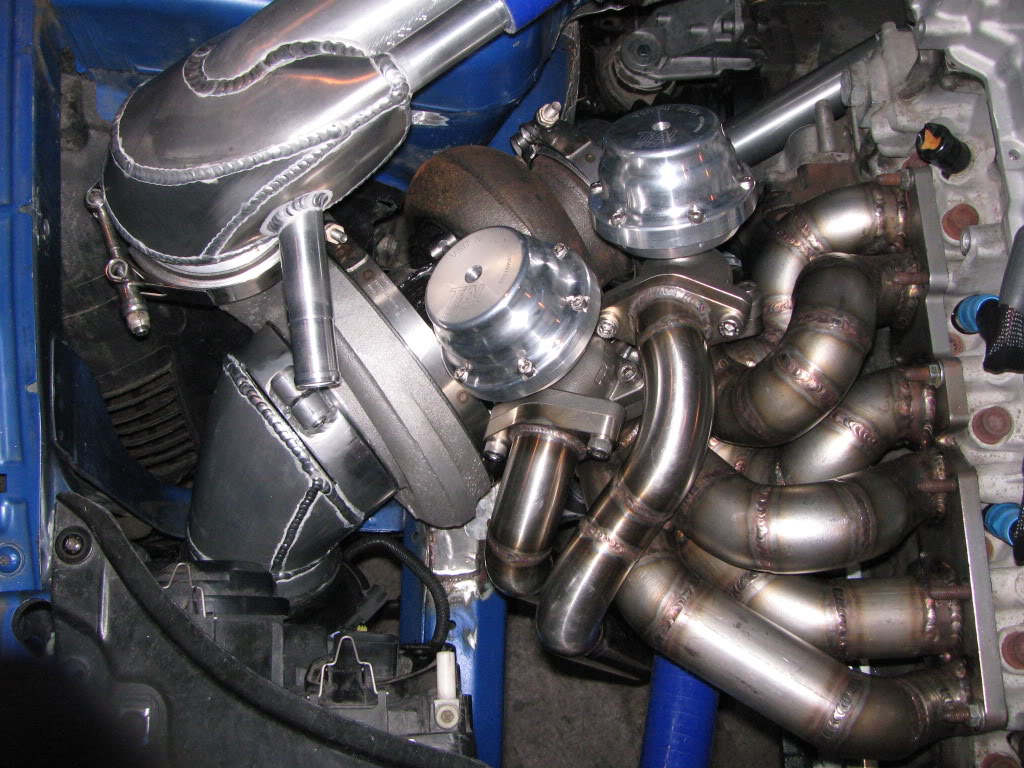
02 INDUCTION CUSTOM EQUAL LENGTH 304 STAINLESS TWIN SCROLL TURBO MANIFOLD
3.5” 304 STAINLESS EXHAUST WITH DYNOMAX STAINLESS ULTRA FLO MUFFLER
4” 304 STAINLESS DOWNPIPE WITH V-BAND FLANGES TAPERING DOWN TO 3.5”
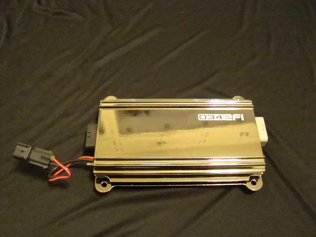
034 EFI STAGE IIC STAND ALONE ENGINE MANAGEMENT 4 BAR ECU
034 EFI PLUG AND PLAY VR6 HARNESS
034 EFI RELAY BOARD (4 RELAYS INC.)
034 EFI BILLET CAM SENSOR ADAPTER
6 BOSCH 3 BAR 96LB (1008CC) INJECTORS LOW IMPEDANCE
(WILL OPERATE AT 4 BAR 1164CC)
034 EFI BILLET FUEL RAIL -8AN INLET/OUTLET
AEROMOTIVE BILLET ADJUSTABLE FUEL PRESSURE REGULATOR
6 034 EFI DIS IGNITION COILS WITH COIL BRACKET SYSTEM
034 EFI VR6 SPARK PLUG WIRES
034 EFI VR6 CHROMOLY SOLID MOUNT ENGINE CRADLE (MODIFIED FOR ENGINE MOUNTS)
CUSTOM ALUMINUM COOLANT HOUSING WITH REMOTE THERMOSTAT
HOWE ALUMINUM RADIATOR
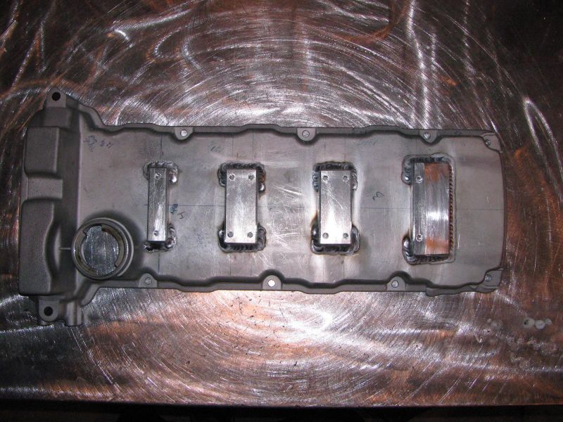
OEM MODIFIED ALUMINUM VALVE COVER
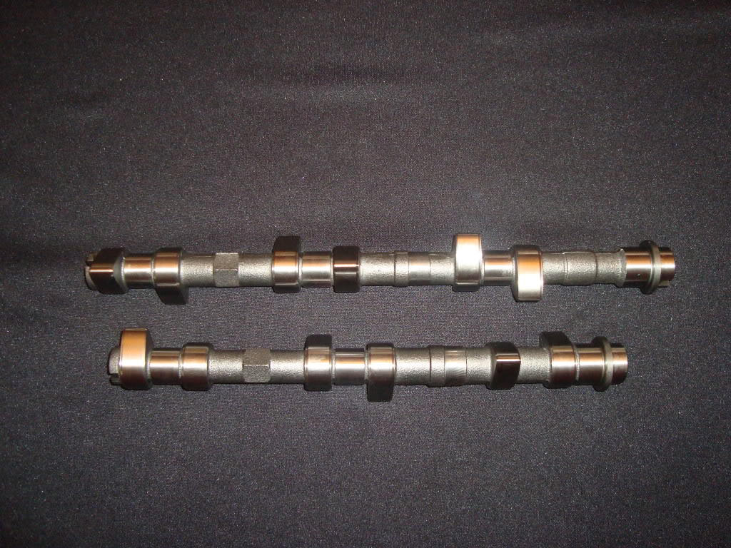
TECHTONICS 268 DEGREE CAMSHAFTS
TECHTONICS TITANIUM RETAINERS
TECHTONICS HEAVY DUTY DUAL VALVE SPRINGS
OEM LIGHT WEIGHT LIFTERS
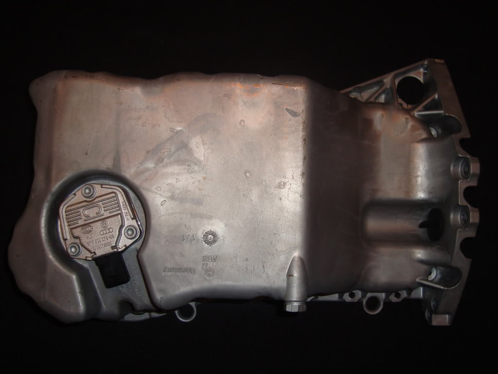
TOUREG OIL PAN
TRANSMISSION/DRIVETRAIN
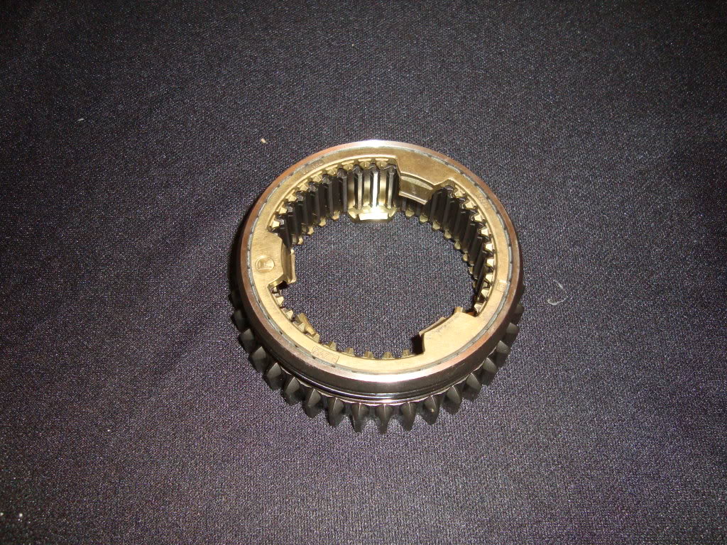
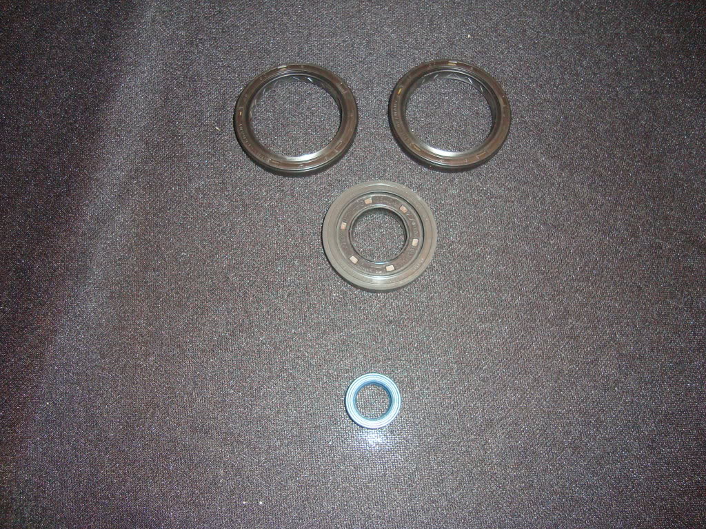
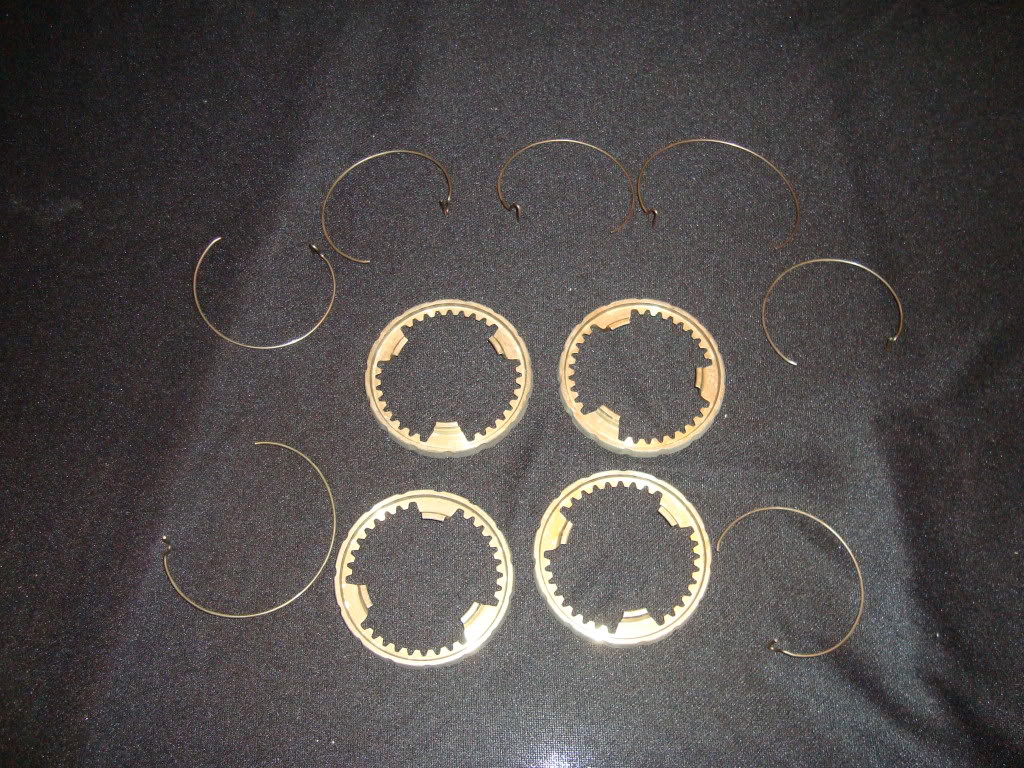
REBUILT 01E TRANSMISSION WITH UPDATED SYNCHROS AND 1-2 SLIDER
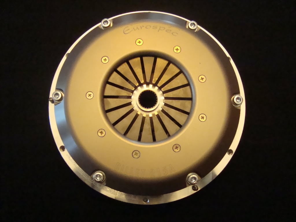
034 EFI/ EUROSPEC BILLET MOTORSPORT CLUTCH
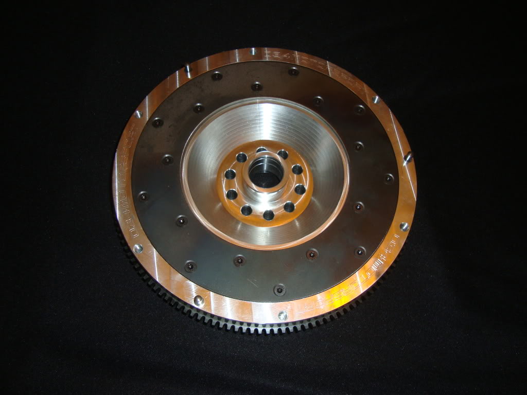
034 VR6 TO 01E BILLET LIGHT WEIGHT FLYWHEEL
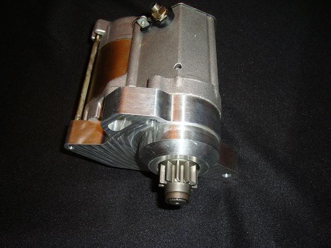
034 EFI BILLET STARTER
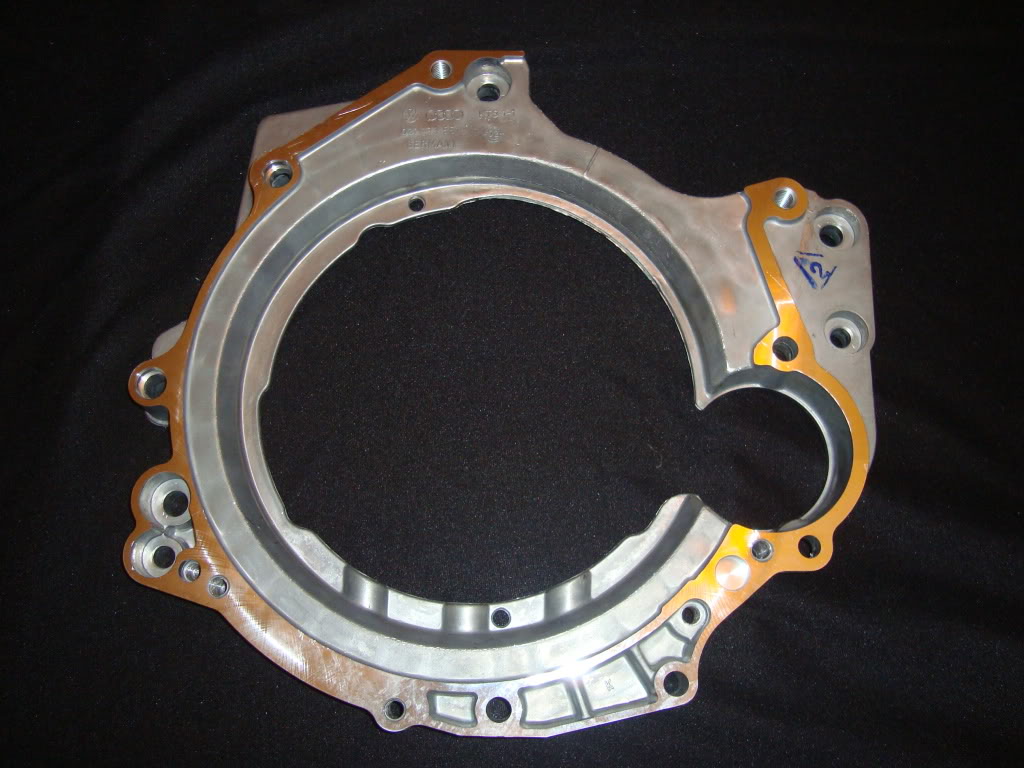
AUDI OEM VR6 TO 01E TRANSMISSION ADAPTER
JHM METAL SHIFTER LINKAGE UPGRADE
JHM SHIFTER STABILIZER BUSHINGS
JHM SHORT THROW SHIFTER
034 EFI STREET DENSITY TRANMISSION MOUNTS
AWE DRIVE TRAIN STABILIZER
APIKOL REAR DIFFERENTIAL MOUNT
APIKOL REAR DIFFERENTIAL CARRIER MOUNTS
034 BILLET REAR DIFFERENTIAL CARRIER
A1-CV TECH AXLES
Here are some progress pix………..
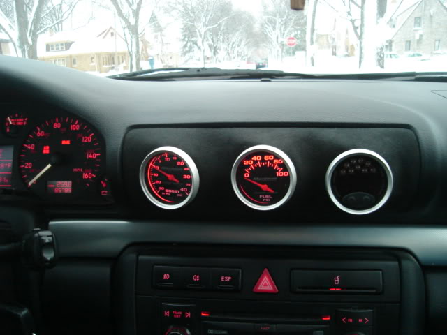
Now I can finally put this 40psi gauge to good use and live up to my screen name!!
Pilot and Co-pilot (wife) chairs

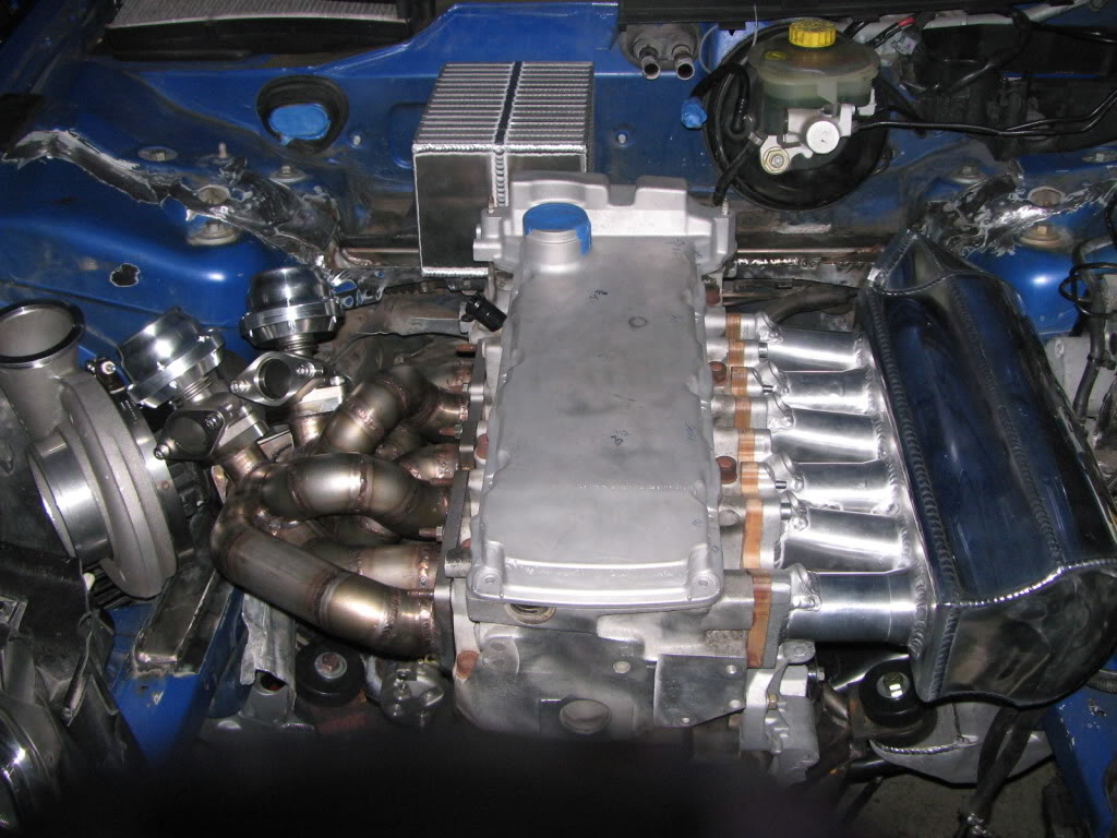
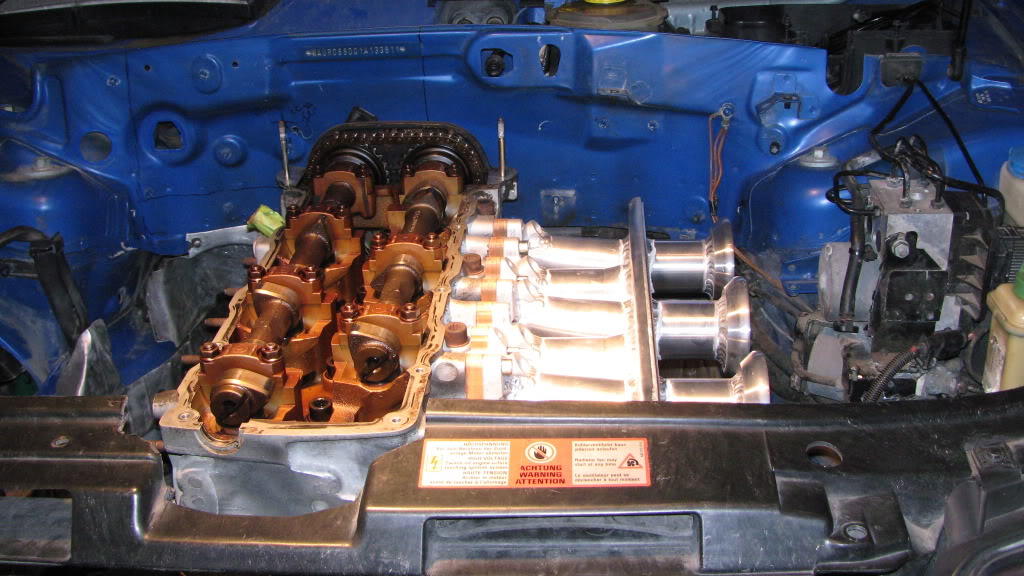
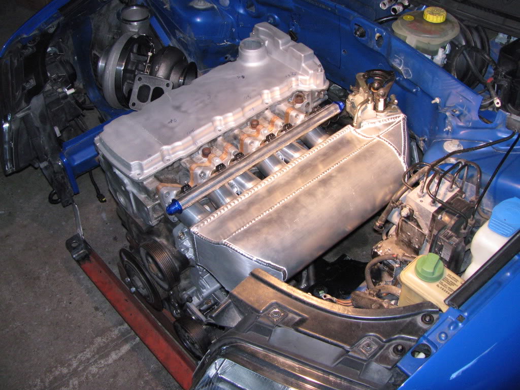
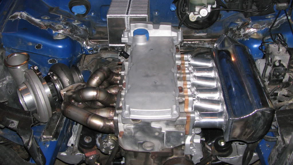
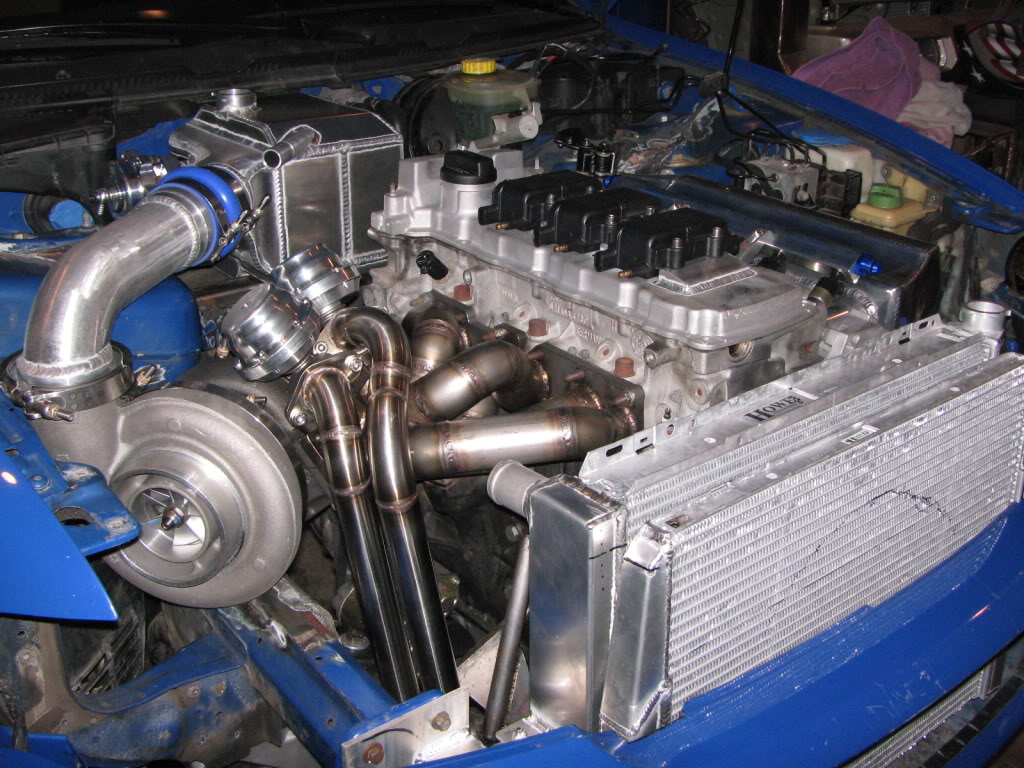
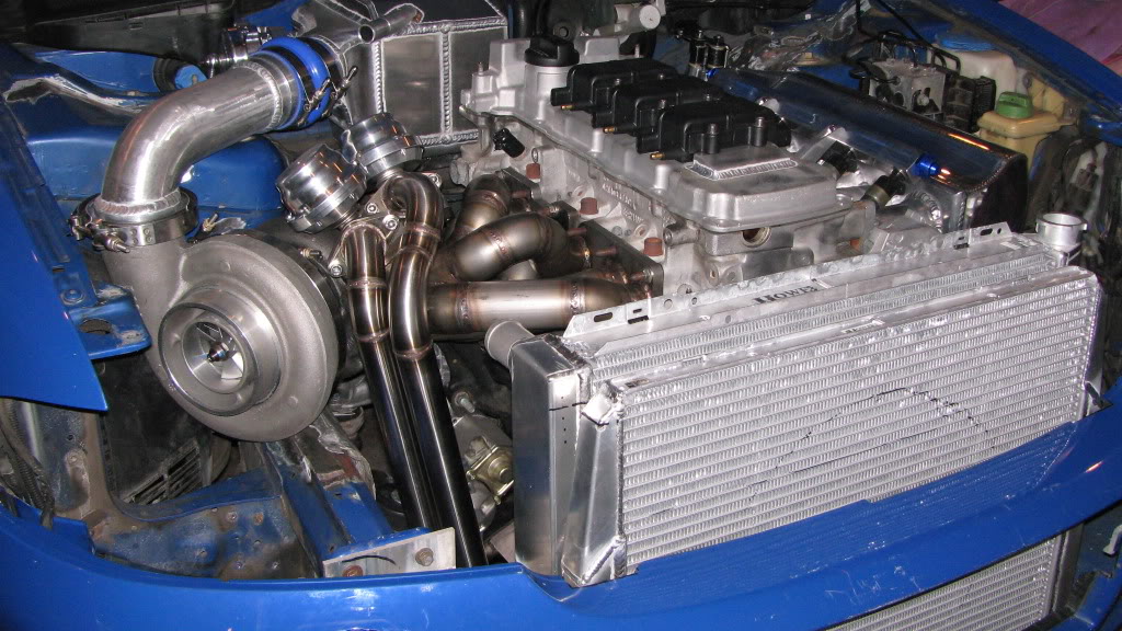
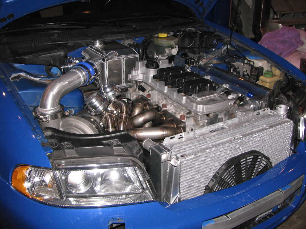
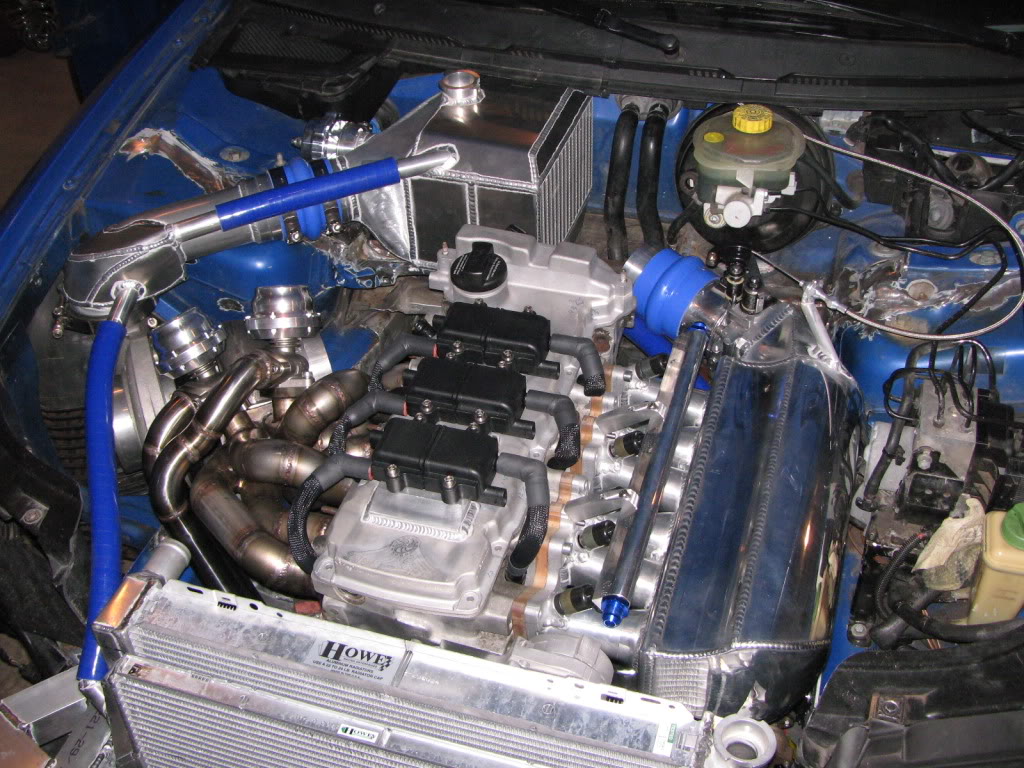
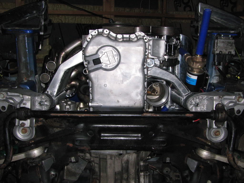
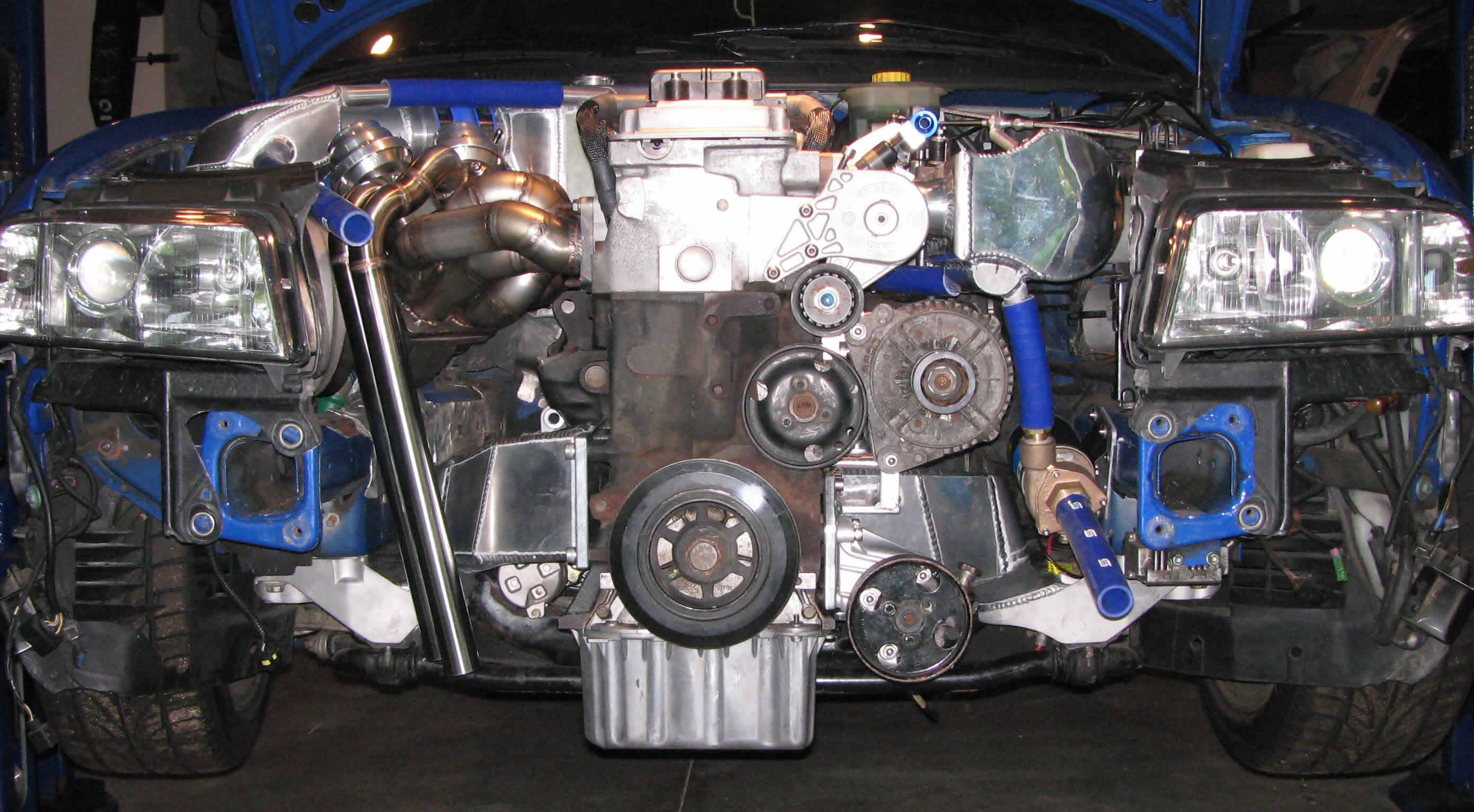
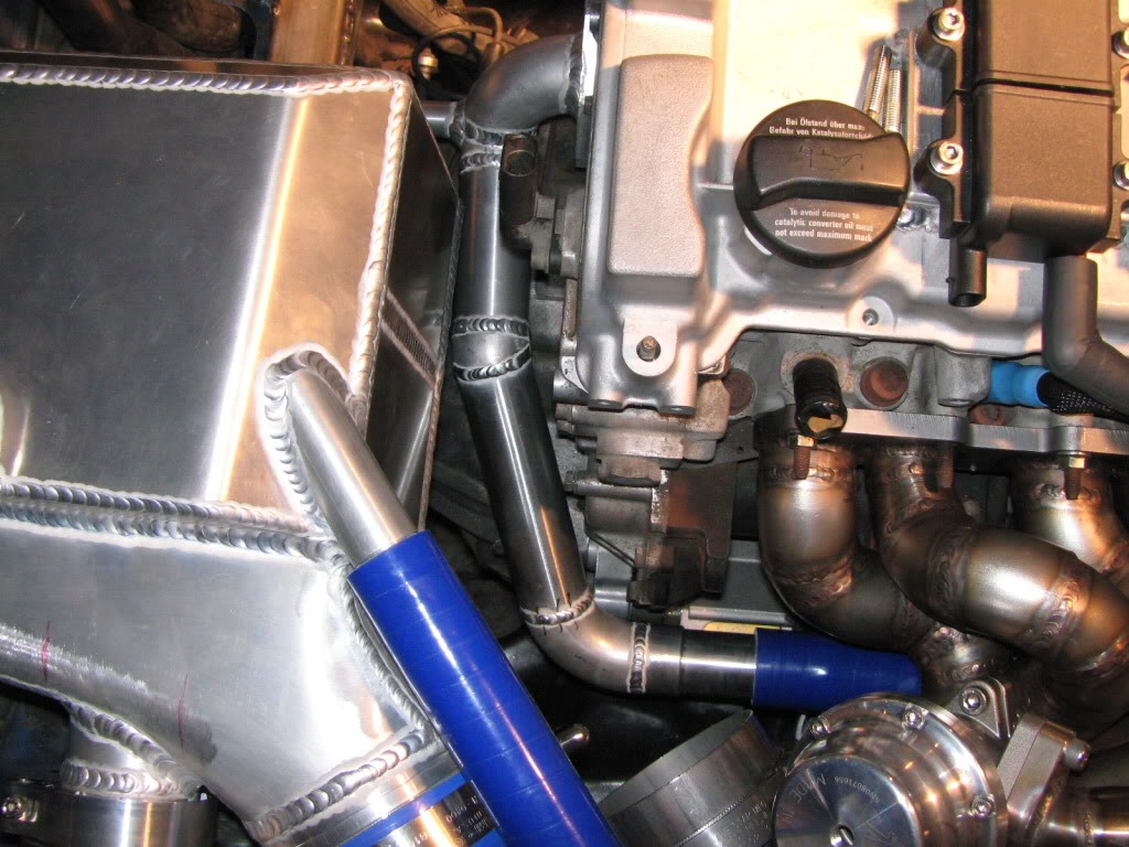
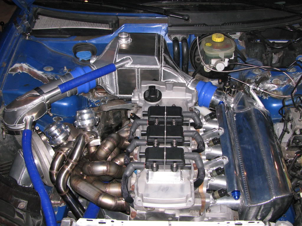
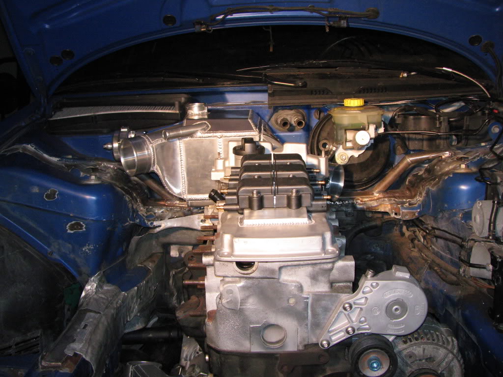
 Now the hoodliner is removed and notice that up to an extra inch of space is available. There is a rise over run of .5″ from the valve cover to 3″ where the valve cover is. Imagine where the turbo is. Remember the turbo is sitting kind of low in its resting place. There is over 5″ of clearance from where the outlet flange is to to the top of the hood. I have a 3″ 90 degree aluminum elbow that will clear the hood by over an inch. Its playing an optical illusion as far as depth is concerned.
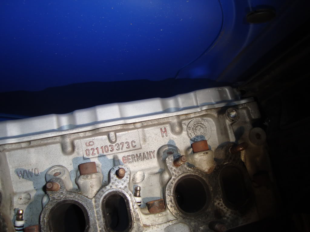
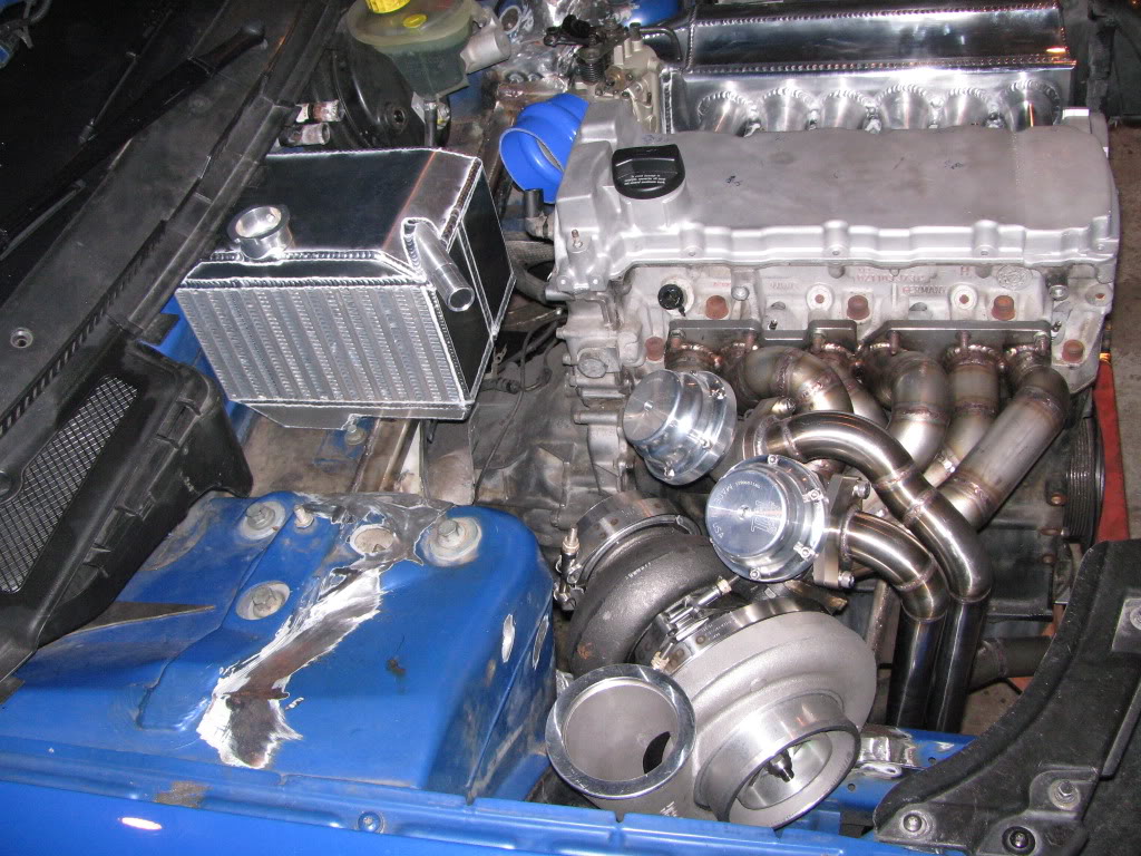
The heater hose spigots will likely have to be modified to clear the outlet discharge side. Plans are to begin the air tank fabbing today.
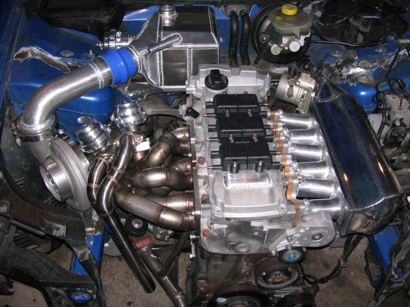
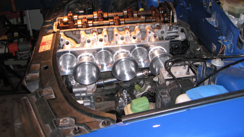
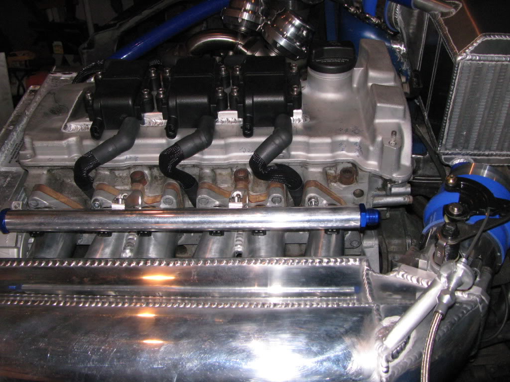
The spark plug wires will have a very short run to each plug and the wiring to the coils will look clean. Form and function…killing two birds with one stone!
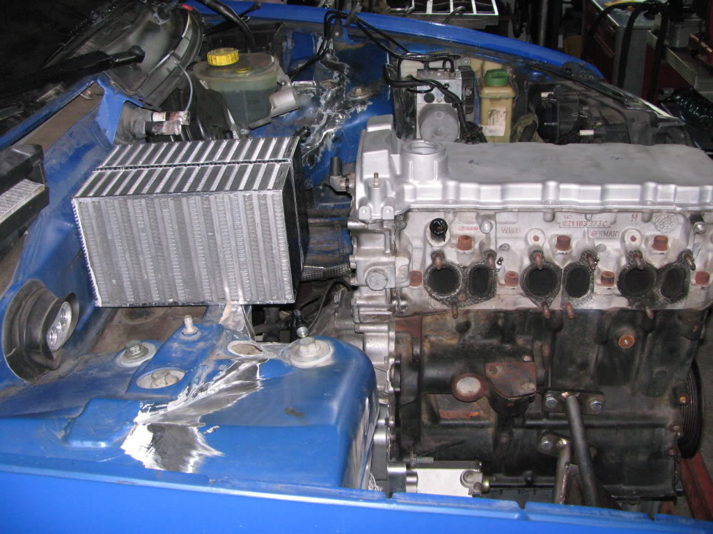
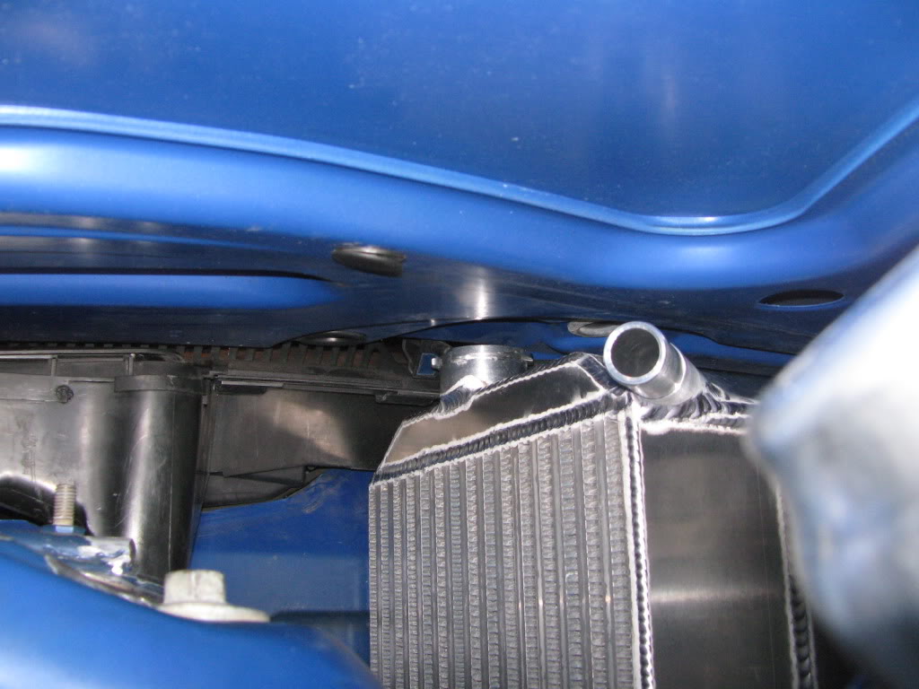
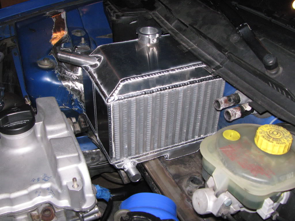
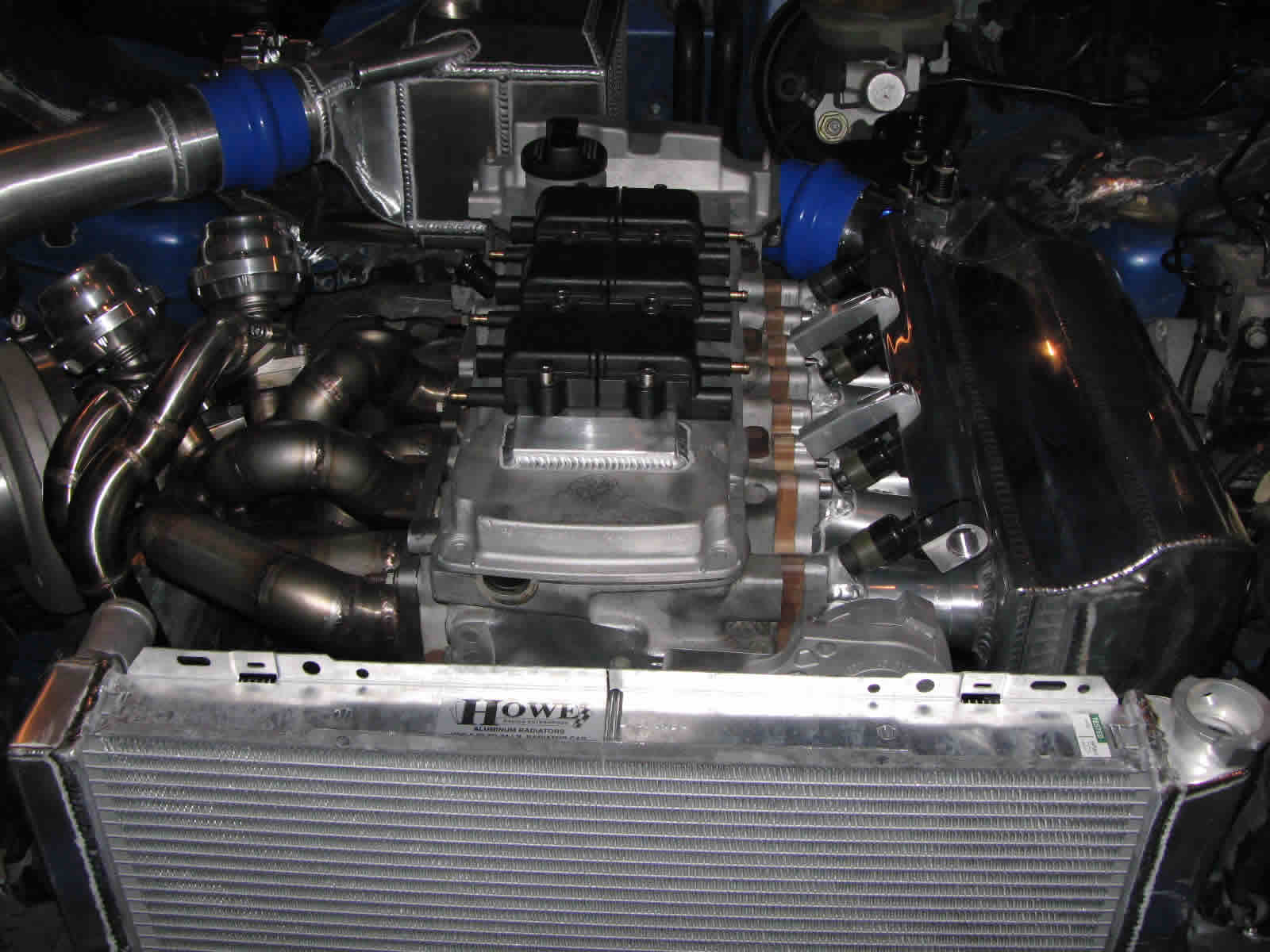
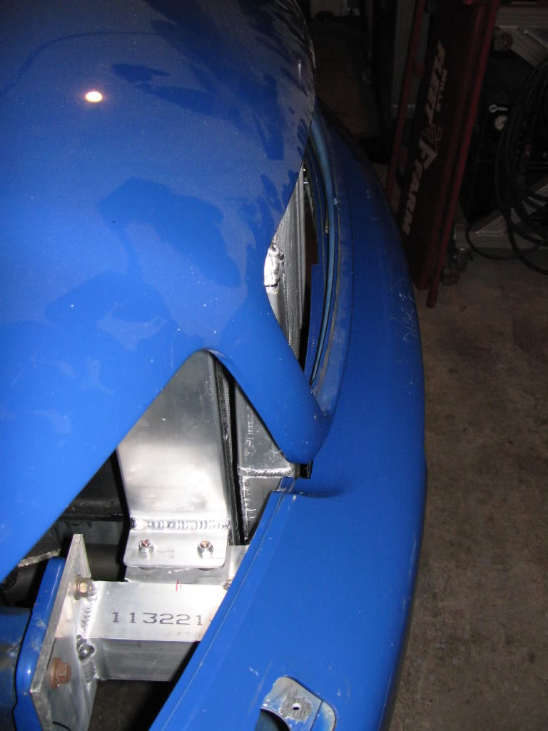
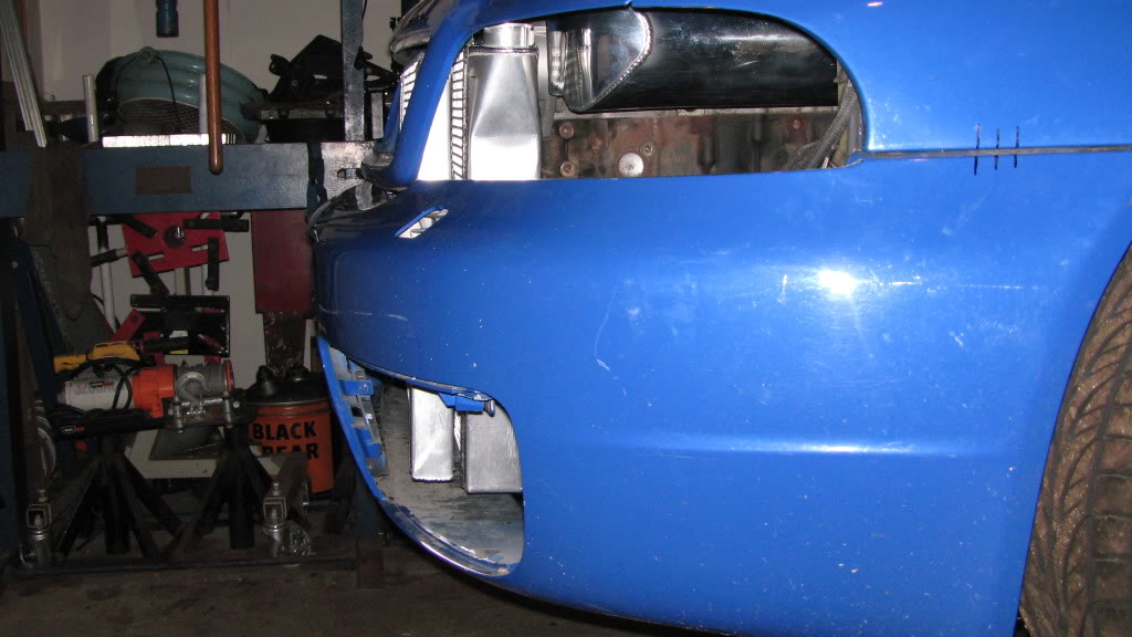
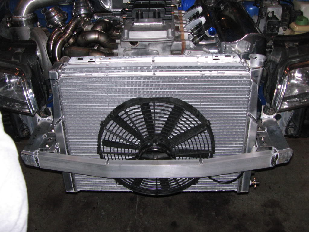
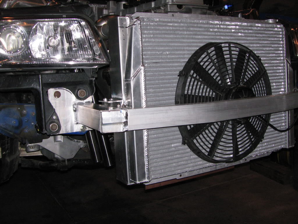
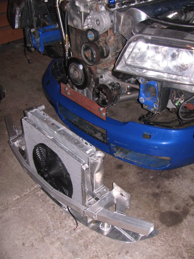
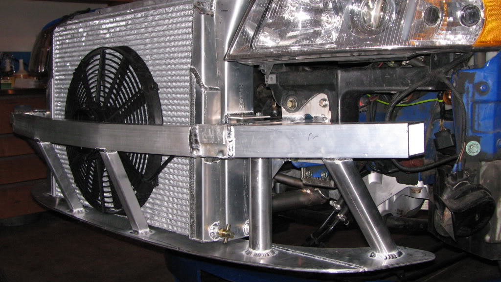
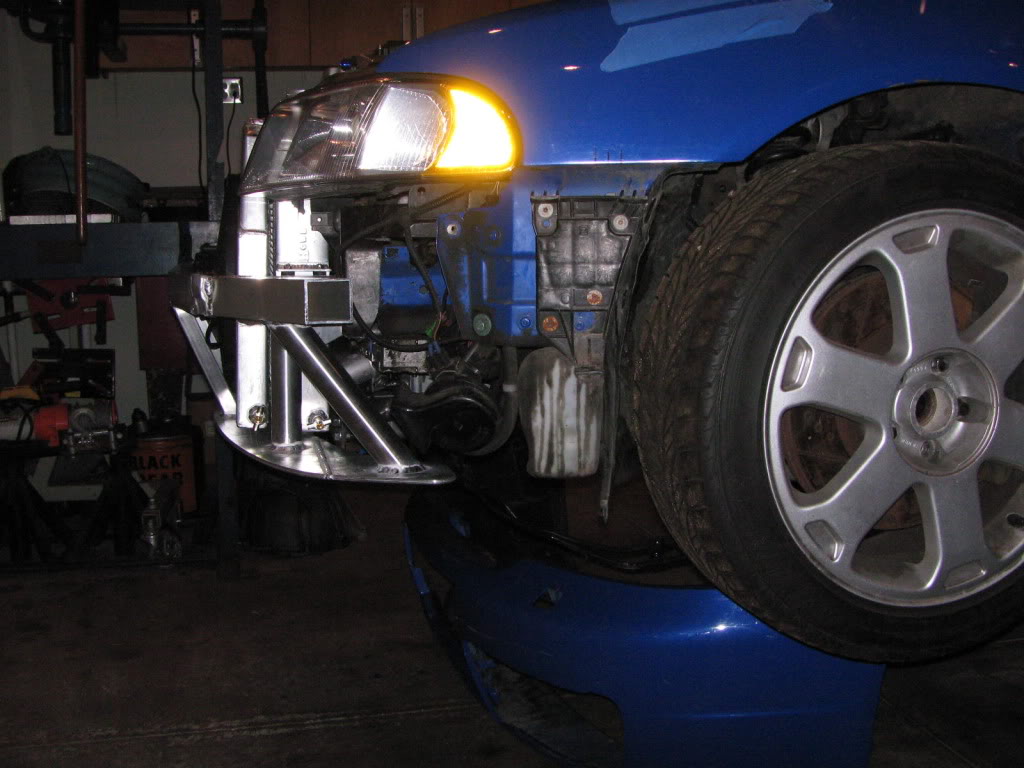
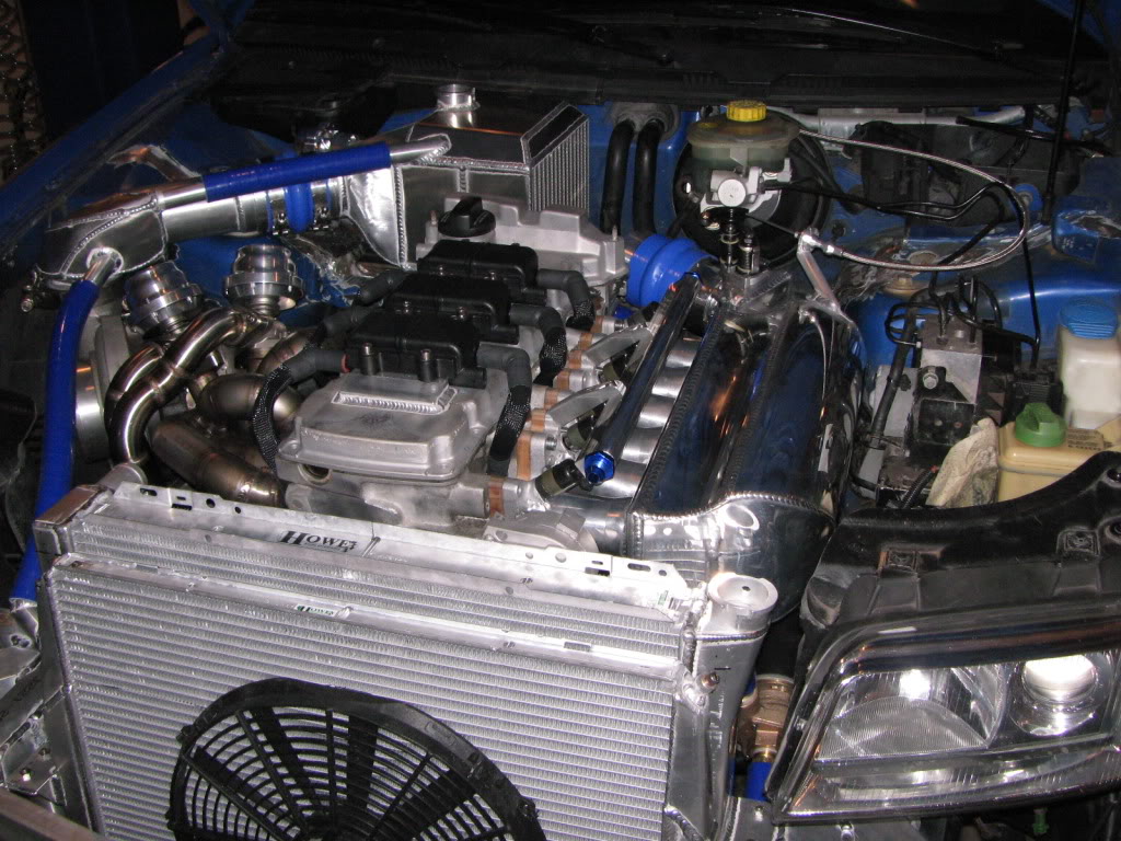
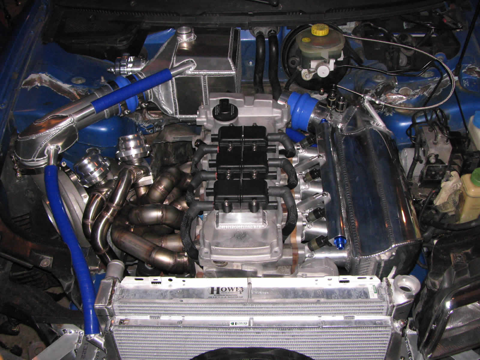
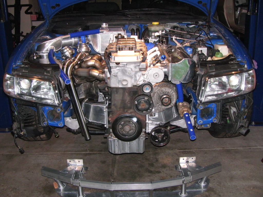
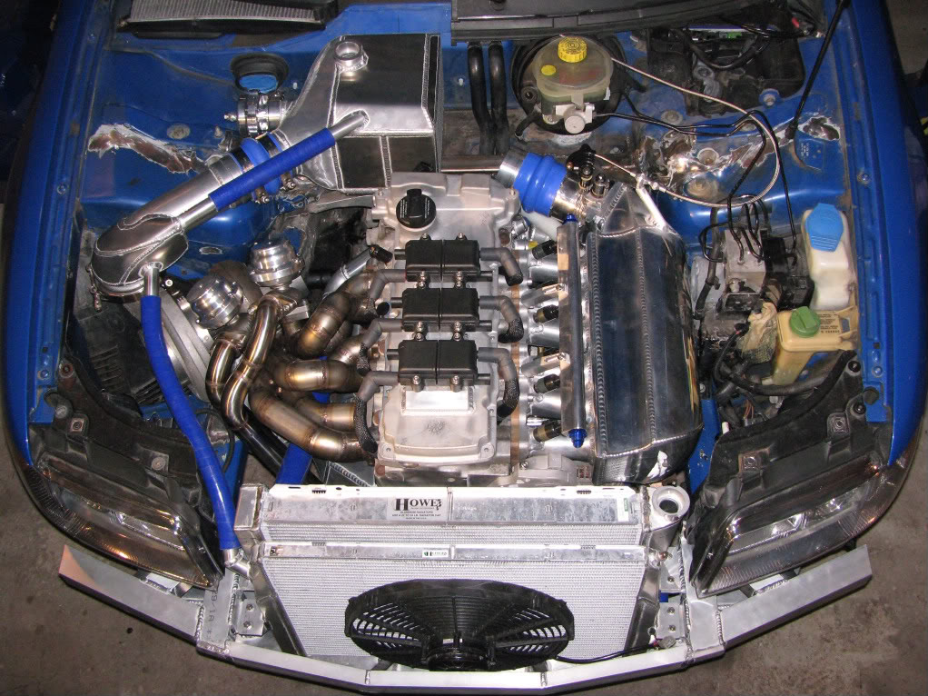
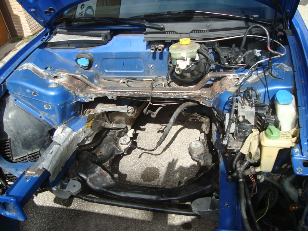
Getting closer. Mounting the radiator was one of the major obstacles along with figuring out a solution to protect the radiator, heat exchanger and engine (not to mention MYSELF and the family) in a frontal collision. I’ll post pix later of that set up.
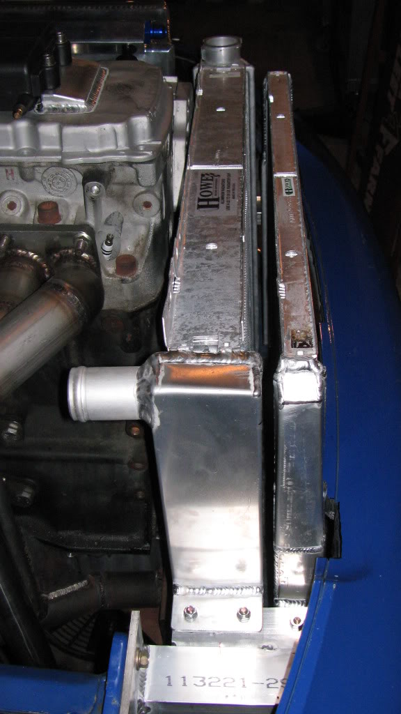
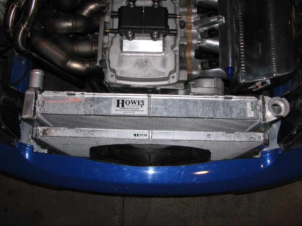
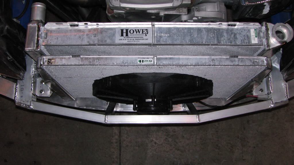
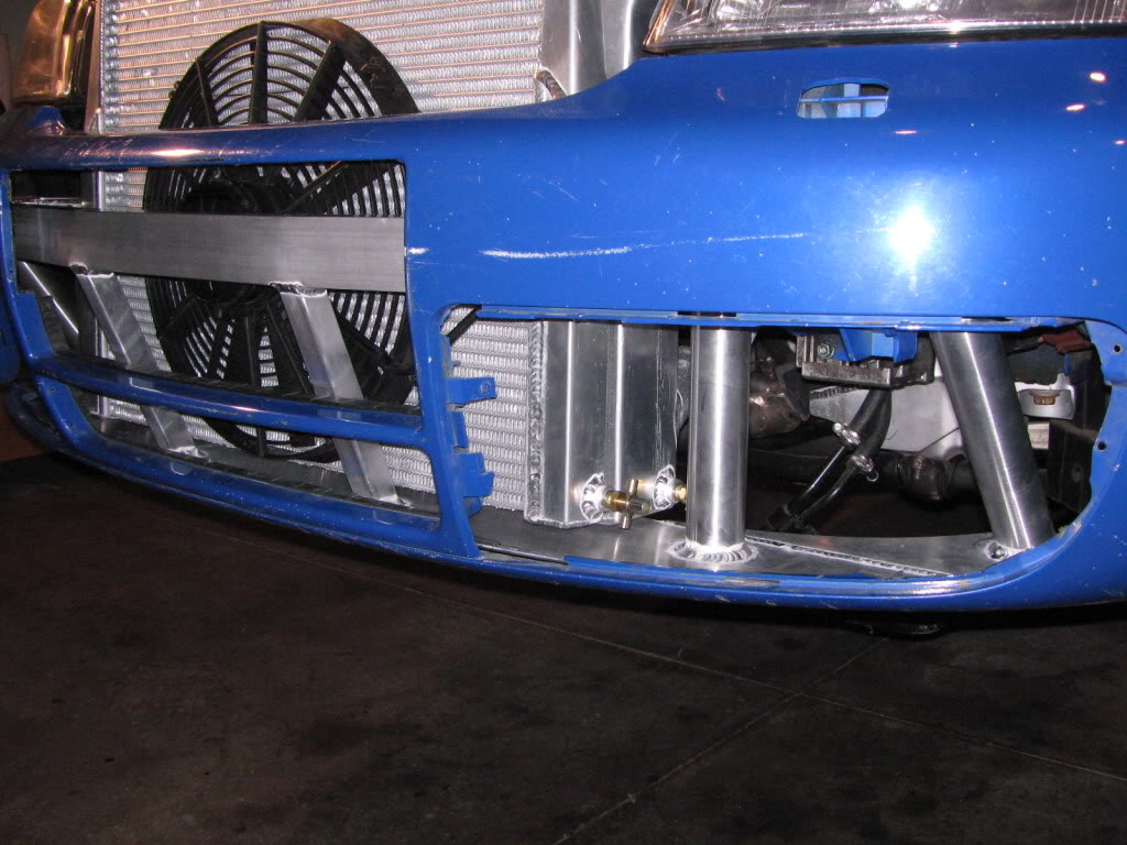
Notice the space between the radiator and the inner edge of the front bumper. There is decent enough room to mount the heat exchanger there. The bumper and support will have to be cut back a little to mount the SPAL fan.
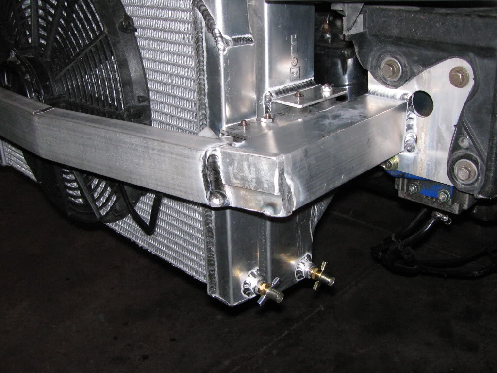
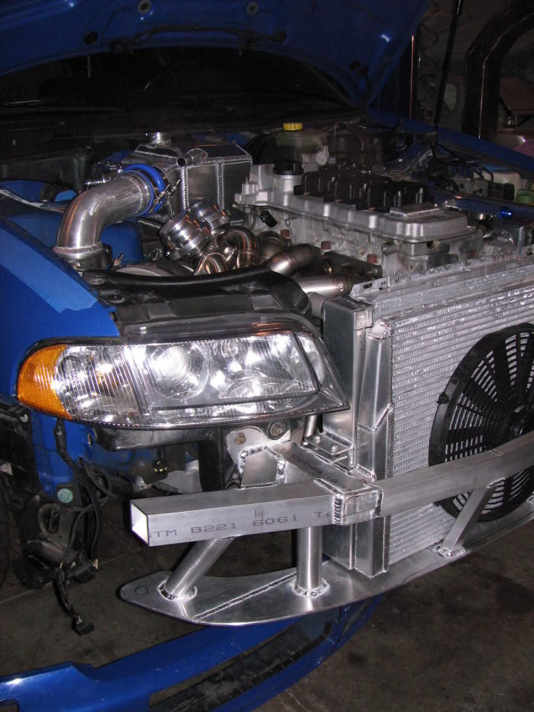
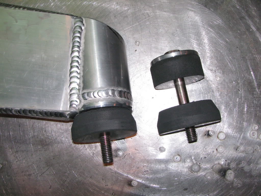
The mounts are iso-mounted using high density rubber. The beauty of this mounting system is that it will be quick and easy to remove the radiator. Look REAL close to the radiator mount on the drivers side, particularly what it’s attached to. That should provide a partial clue of the frontal system design.
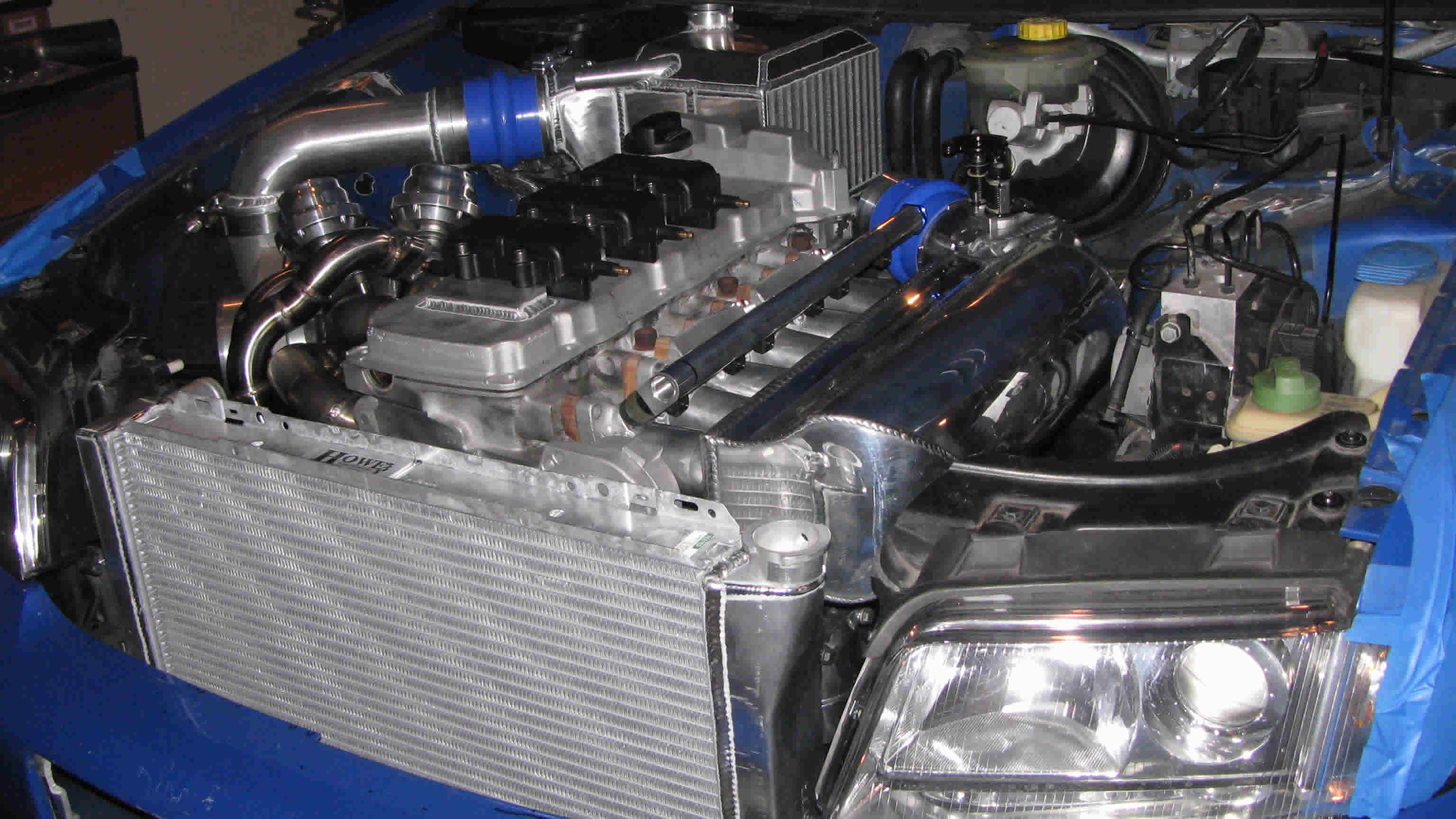
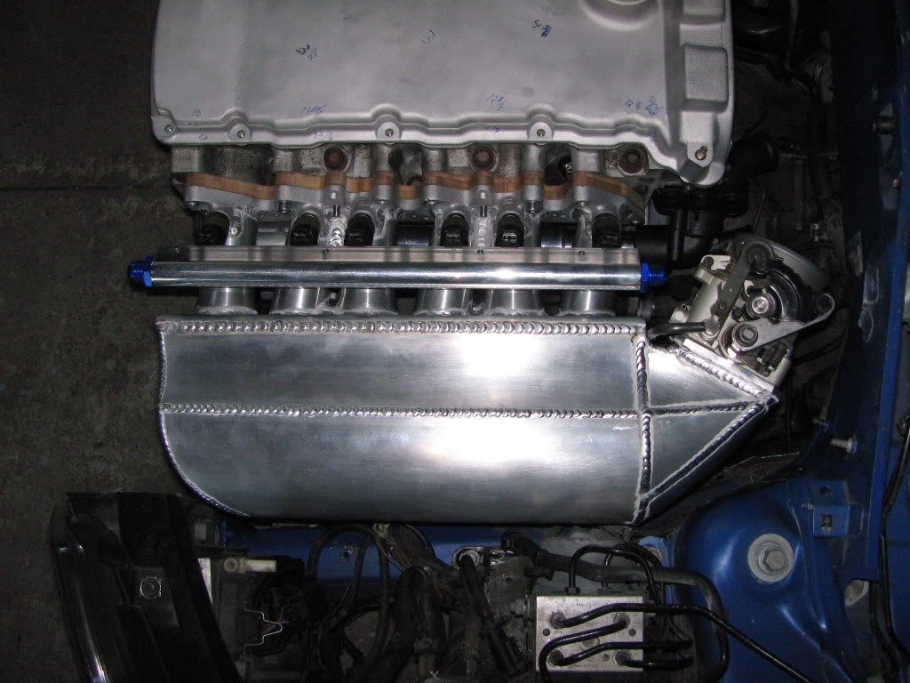
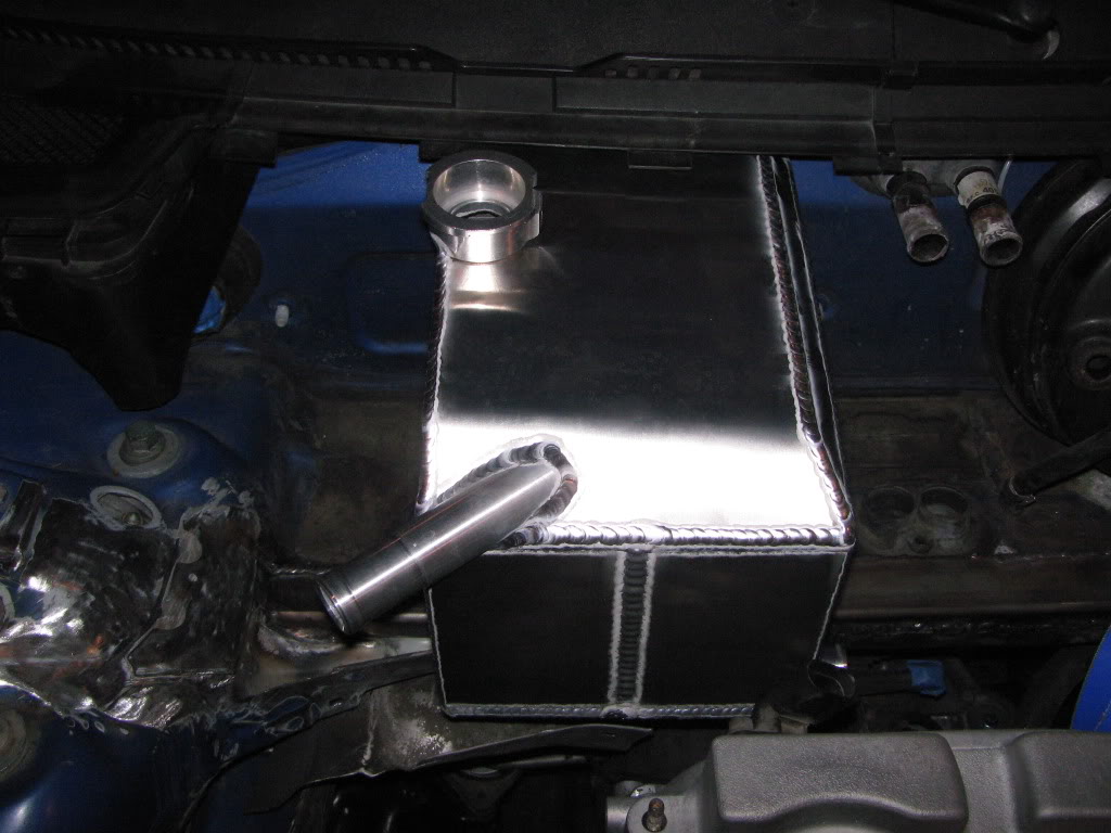
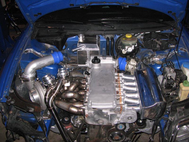
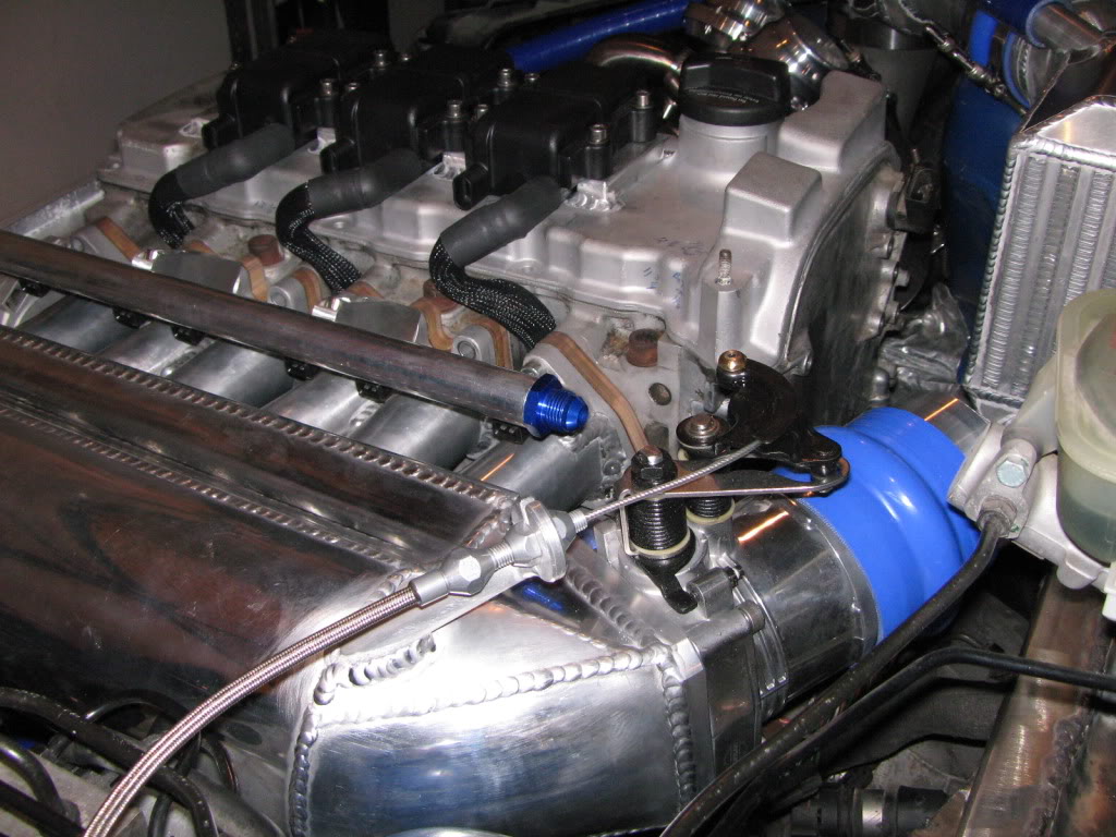
Also, if you take a close look, the throttle body is finished and the aluminum inlet tube has been made. The driver’s side air tank is the last remaining part that needs to be completed and the A/W system is finished.
Here are some quick shots of the fabbed billet fuel rail mounts.
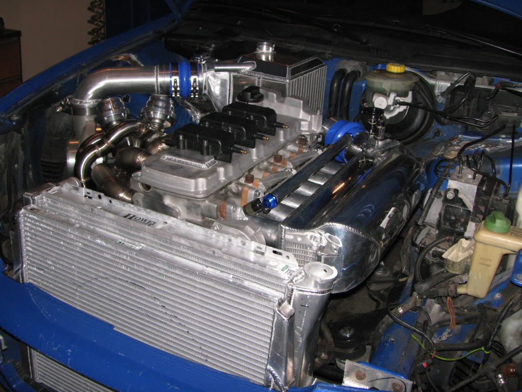
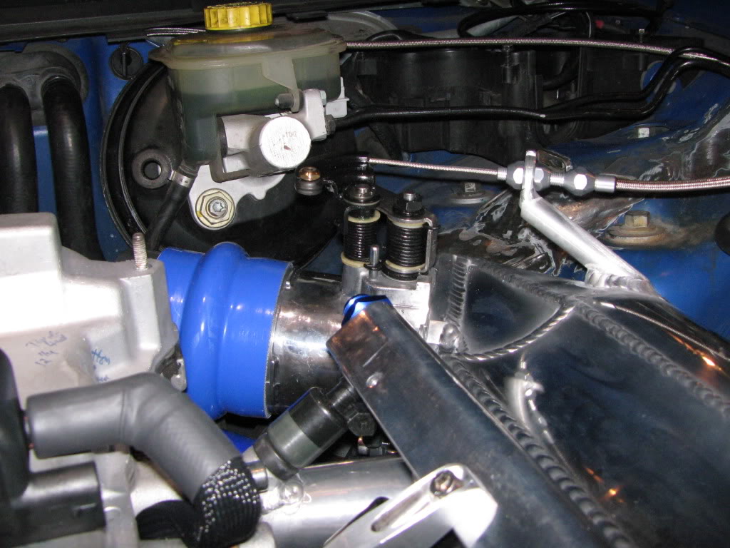
cable was from the unit 034 provided me along with a LOKAR unit I already had. Even the black factory triangle that fits
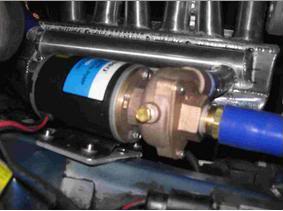
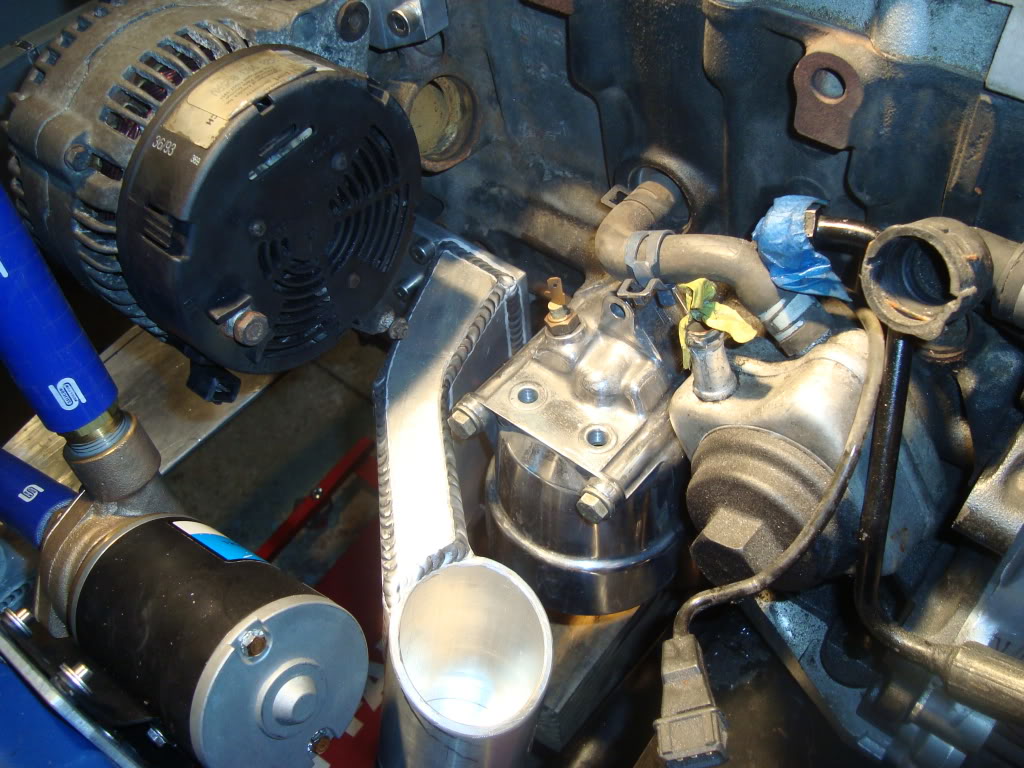
on the firewall was used. It fits like a OEM unit!The water pump for the AWIC system is mounted and the hoses have been positioned. The water flow path runs in the
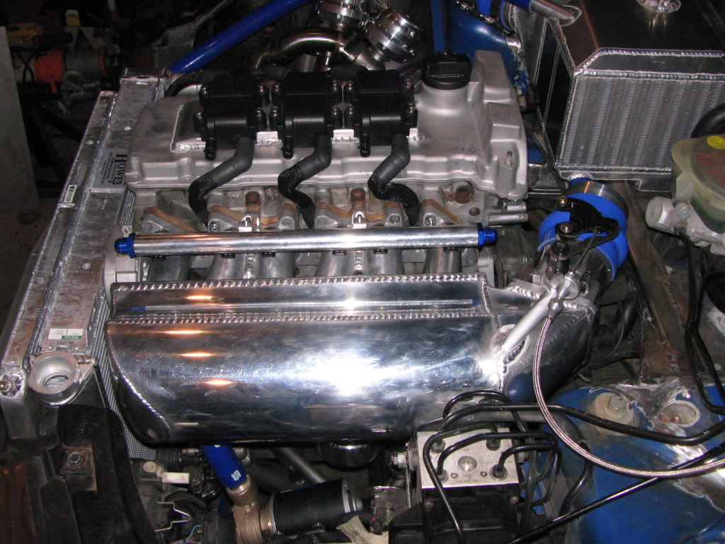
opposite direction of the air flow path. The water pump first sends the cooling medium from the heat exchanger to cool the
intake manifold through a channel underneath the plenum (approx 1 liter of volume). Next the medium flows to the AWIC.
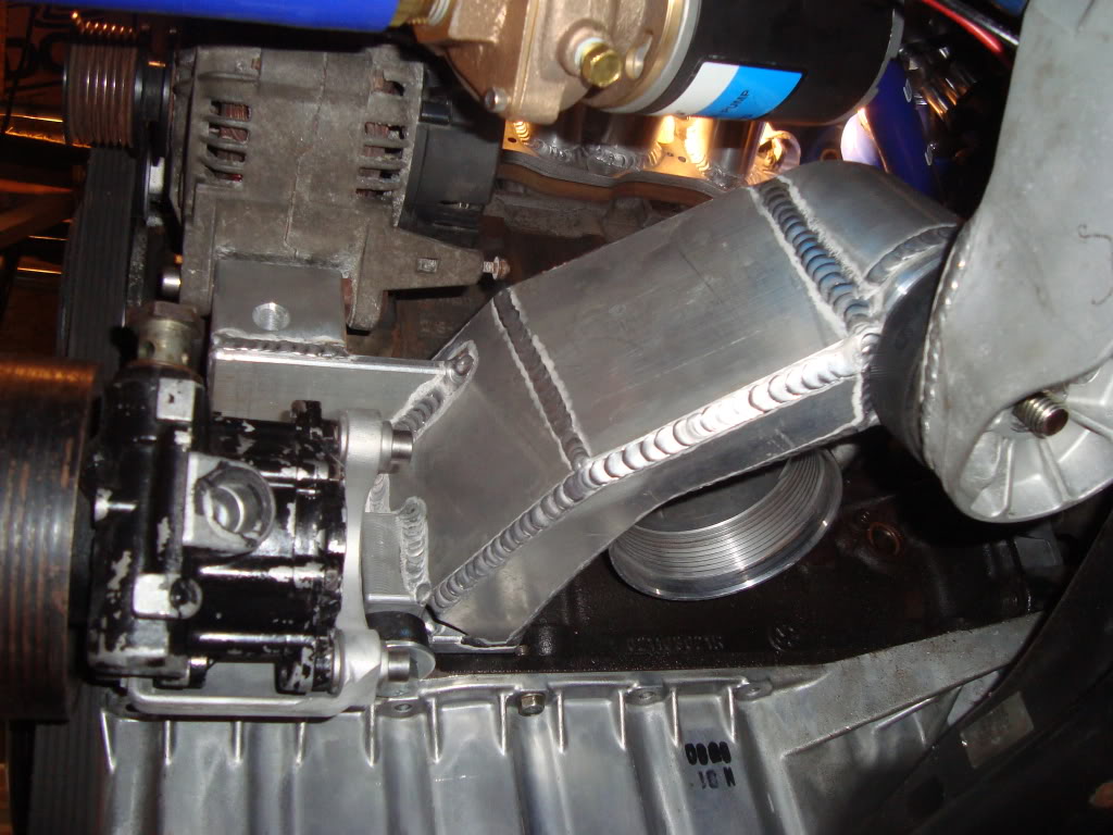
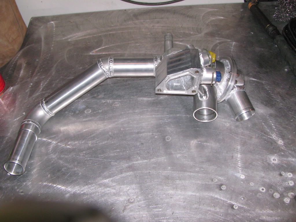
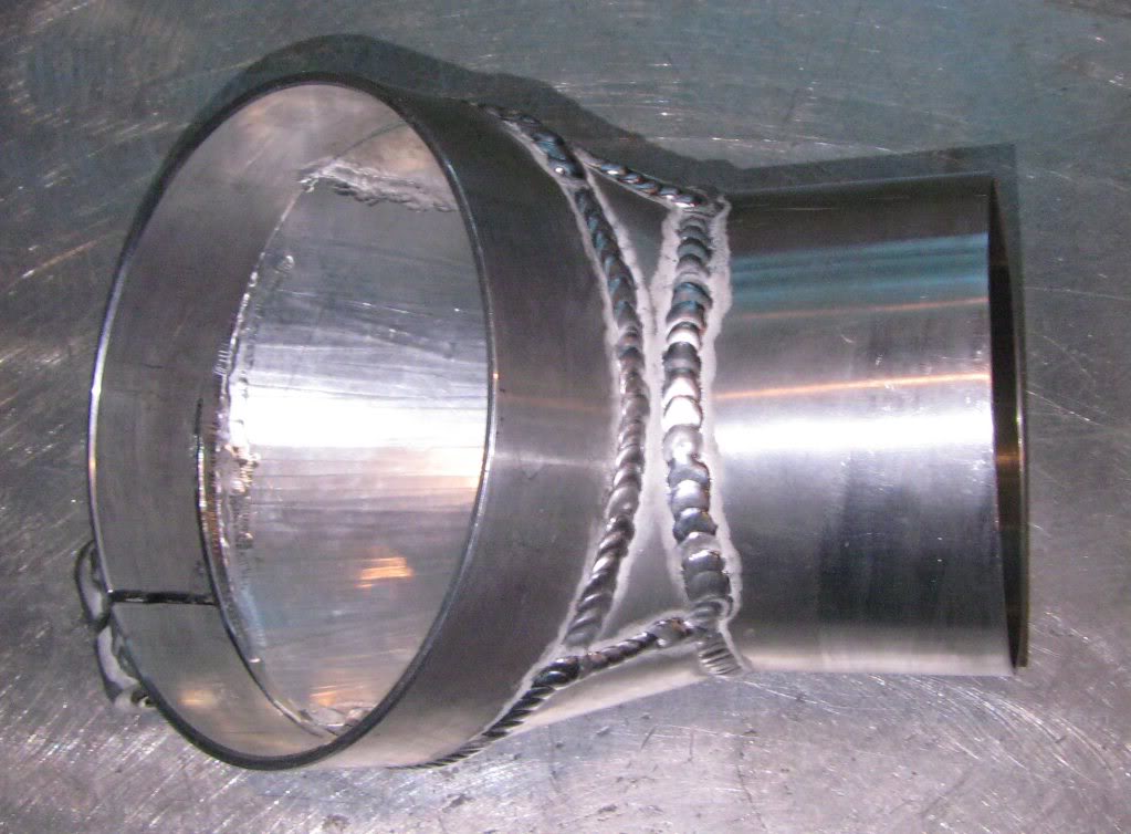
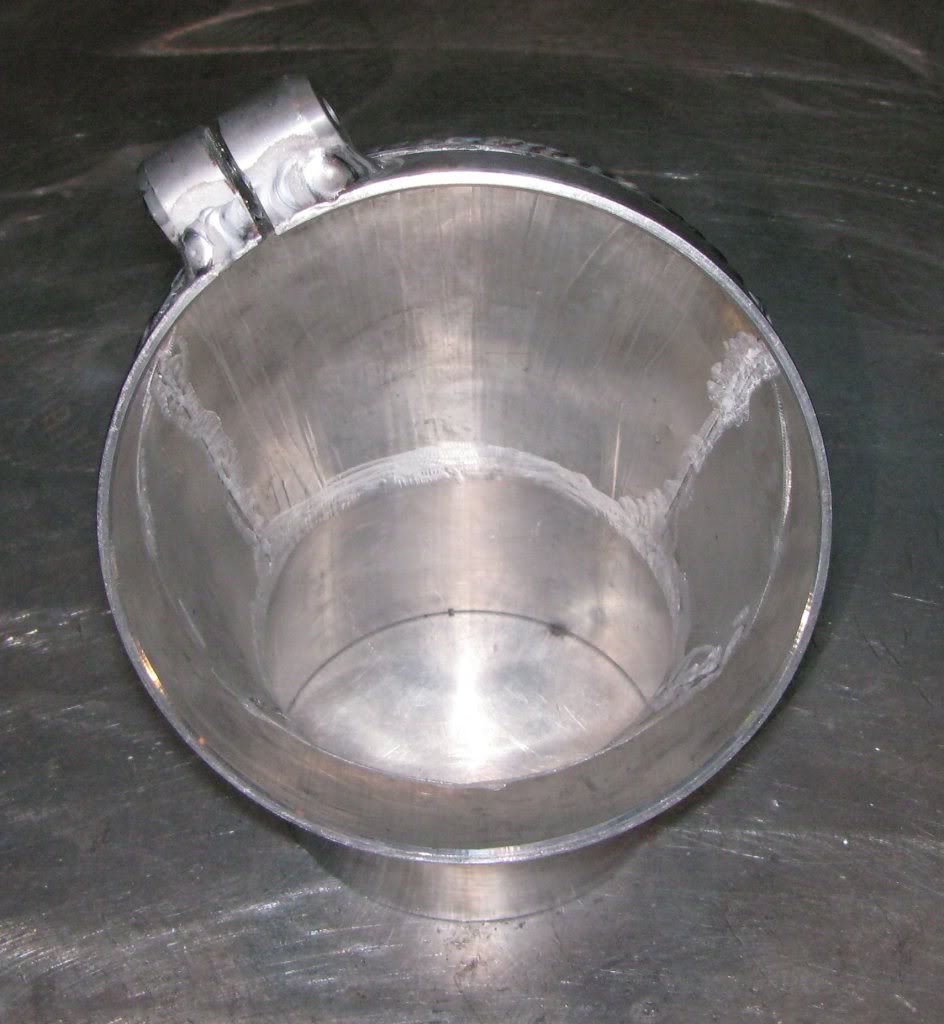
After that, the compressor discharge pipe has been modified and now incorporates an intercooled plenum around it. It is
designed with an internal baffle that swirls the water around the neck 360 degrees and exits directly into the heat exchanger.
It is designed to reduce the inlet temperature before the AWIC and thus to further reduce the entire intake temps.
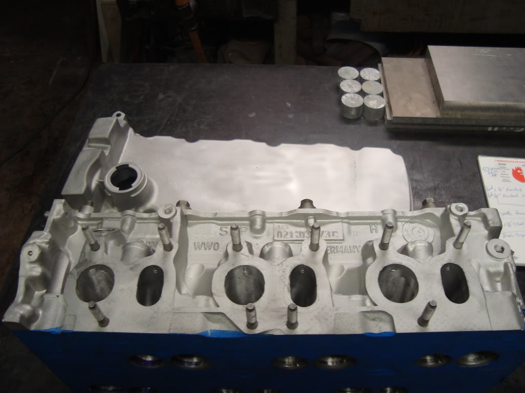
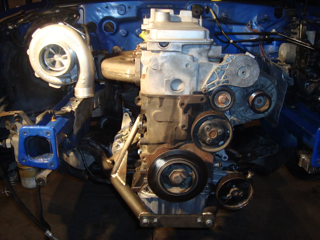
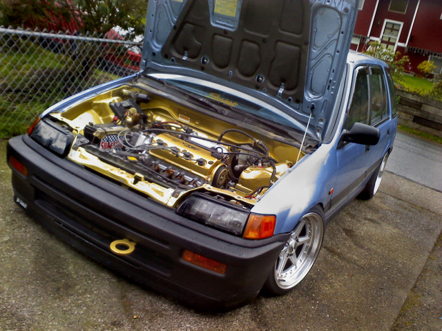
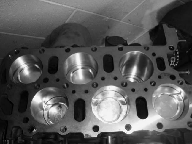 Here is a quick shot of the shortblock. It is a 2.9L with JE 9:1 polished pistons and Eurospec rods. Honestly, I suspect that 034,
Eurospec and Integrated Engineering rods are all the same. I might be wrong, but after weighing IE and Eurospec units
I found that they weigh EXACTLY the same. The good thing is that all 12 rods were dead on the same weight. Visibly
they look the same too. I’ve seen these rods support well over 1000chp so I feel confident but at the same time I probably just
jinxed myself.On another note I decided to upgrade to 288 TT cams. I need a little more, OK a lot more RPM than the 268’s will provide. The head
is getting resurfaced and the longblock should be assembled this weekend. I’m going to use the mock up VR6 already in the car
as a spare to build over the winter. I intend to build that engine with a little higher compression, internal coatings and a few other
tricks. It’s inevitable that something is going to give sooner or later so I might as well be prepared.
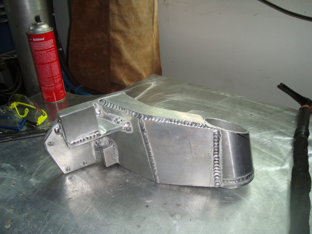
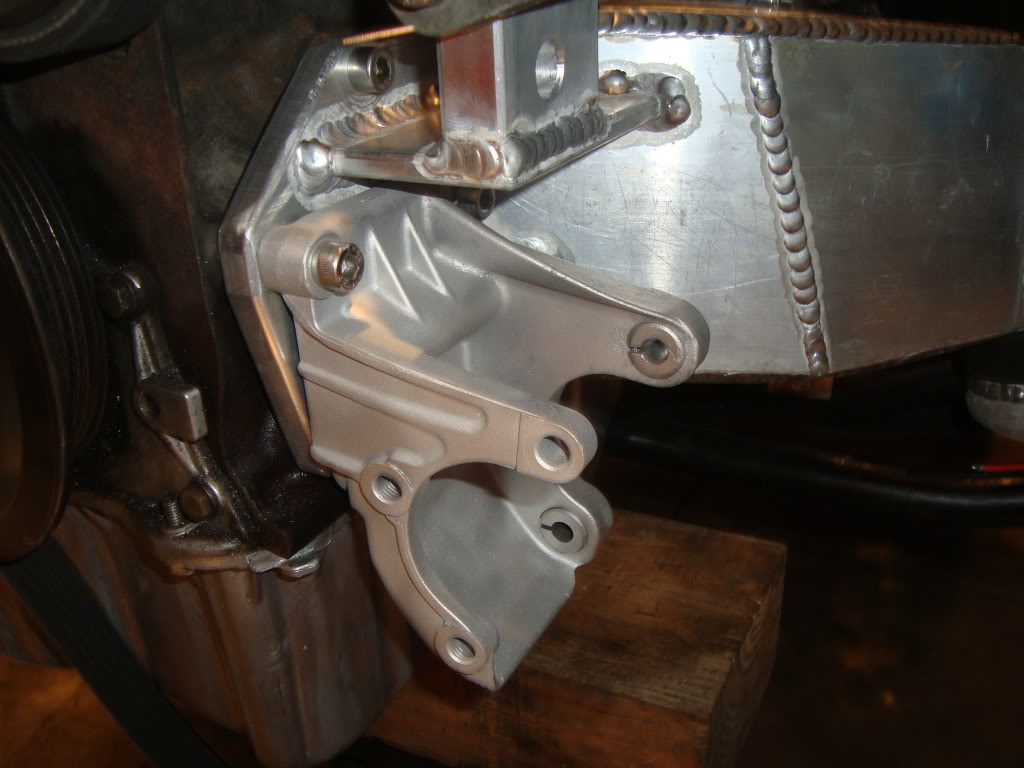
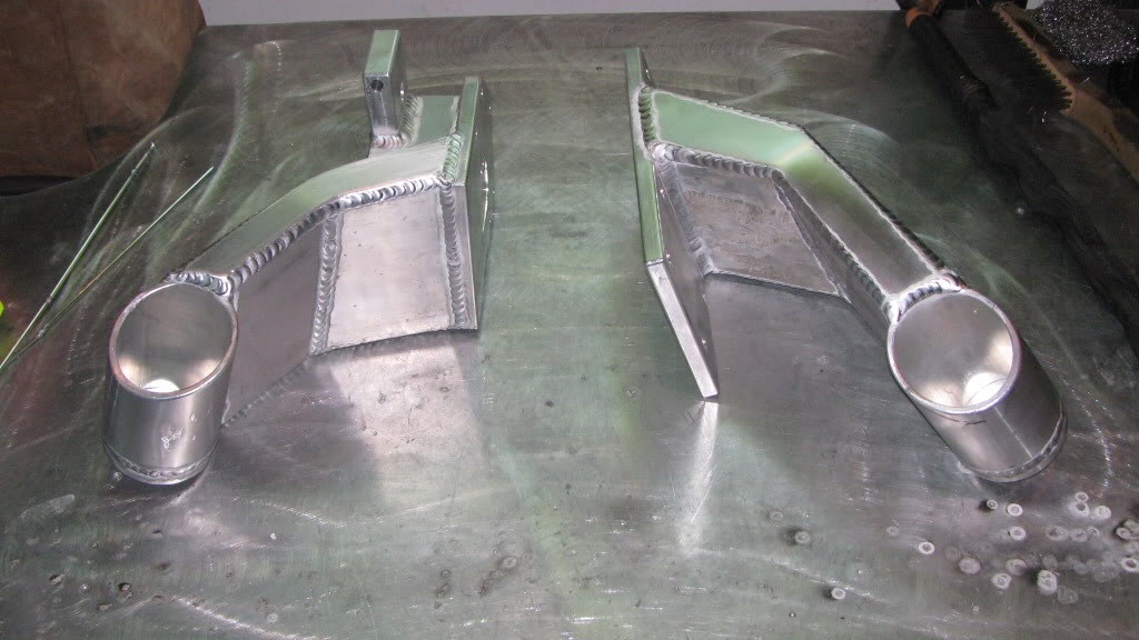
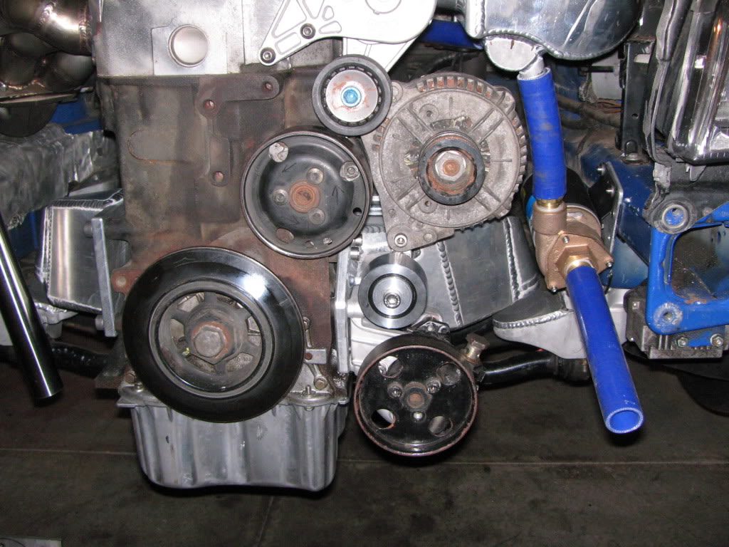
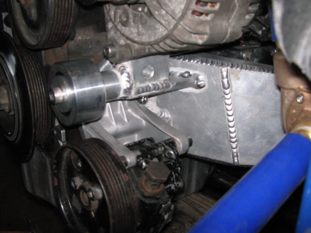
will function as the lower alternator bracket, power steering bracket AND driver’s side engine mount. The driver’s side should be
completed by Sunday or Monday at the latest.
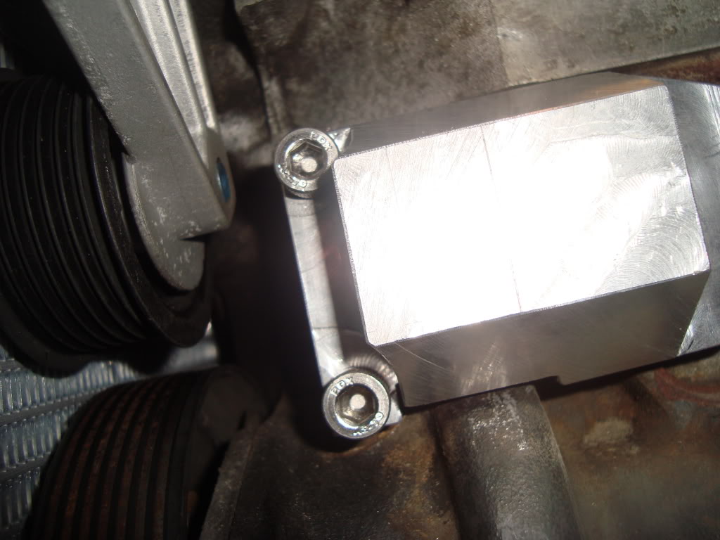
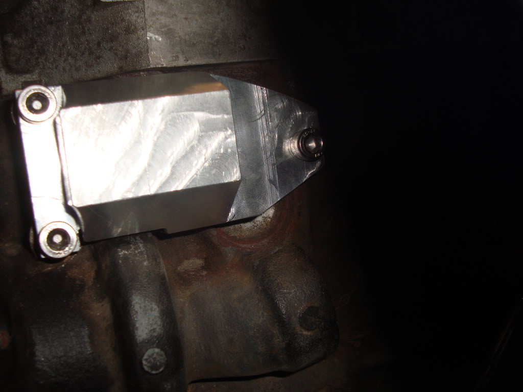
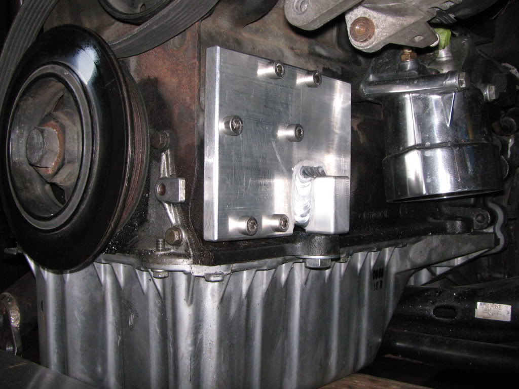
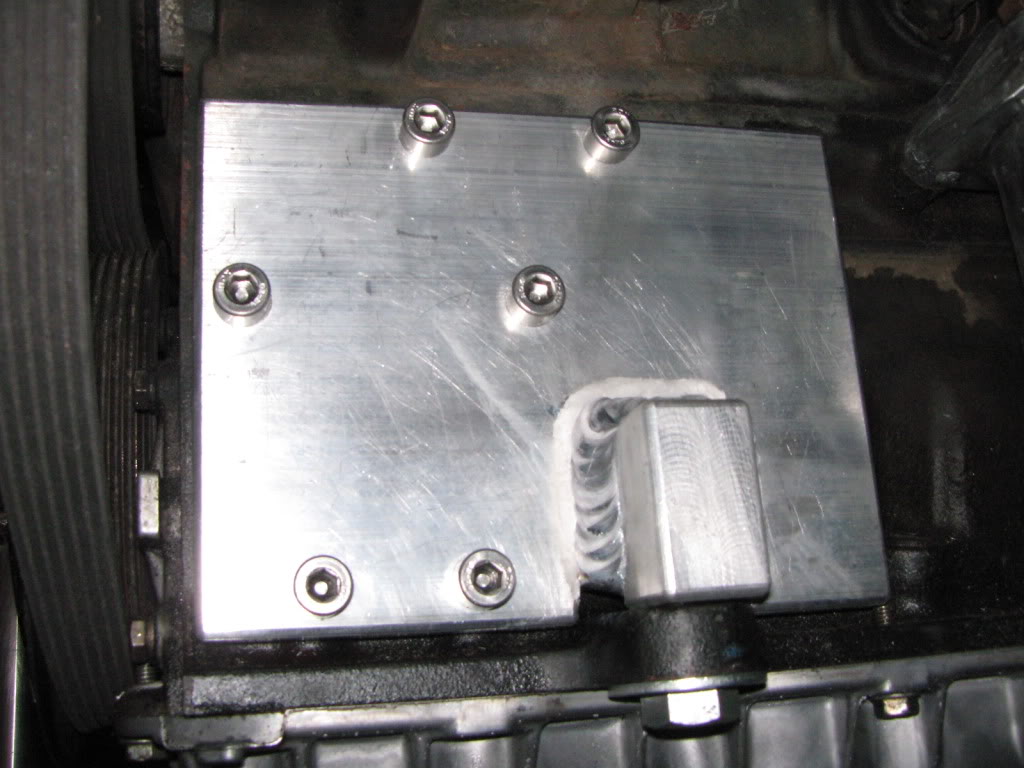
Next, is the actual engine mount welded to the plate. Notice the upper alternator bracket.
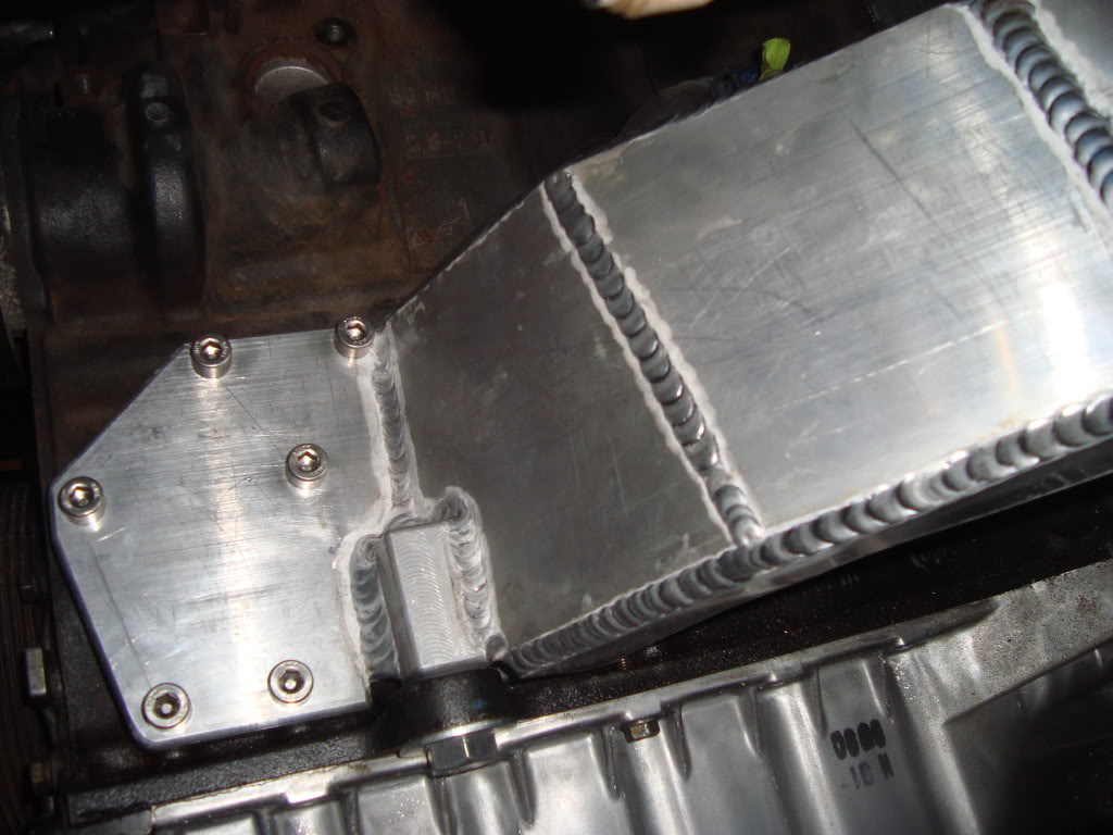
This is the lower alternator bracket that was just welded onto the main assembly.
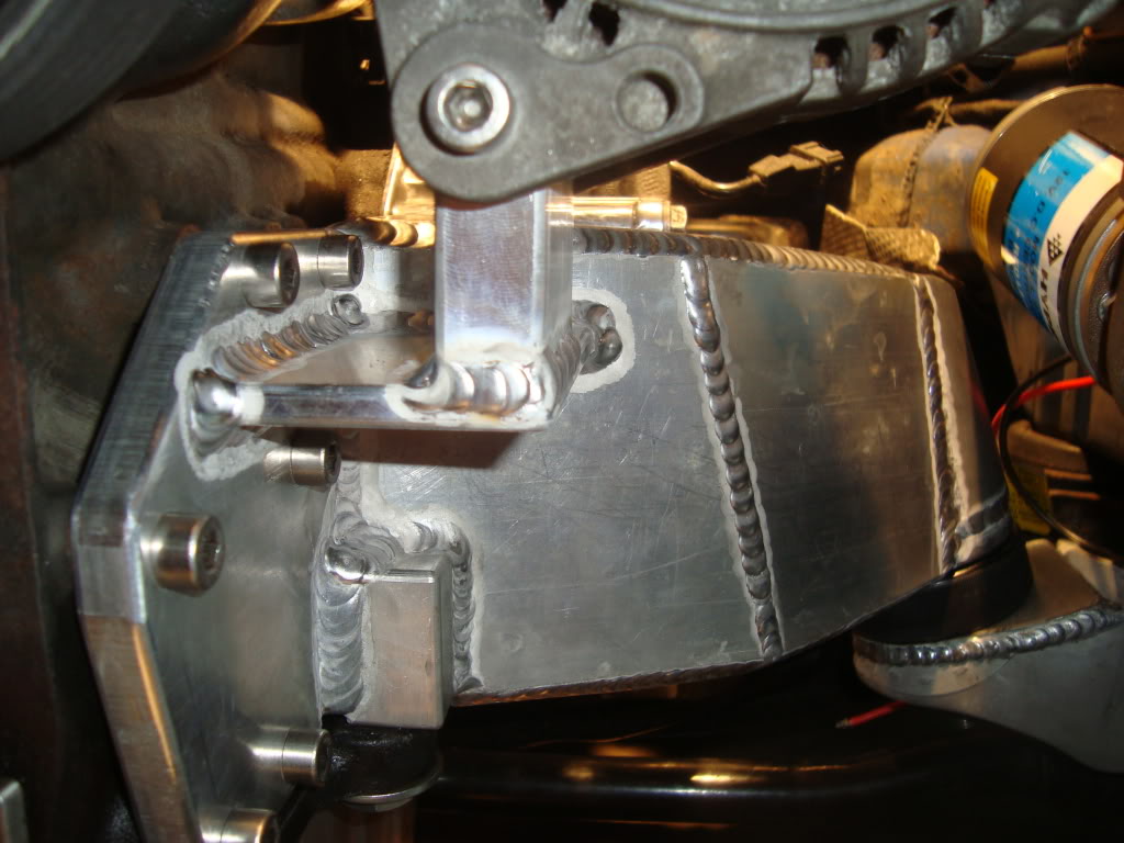
A pass through hole was drilled and chamfered to reach the inner bolt connecting the bracket to the block.
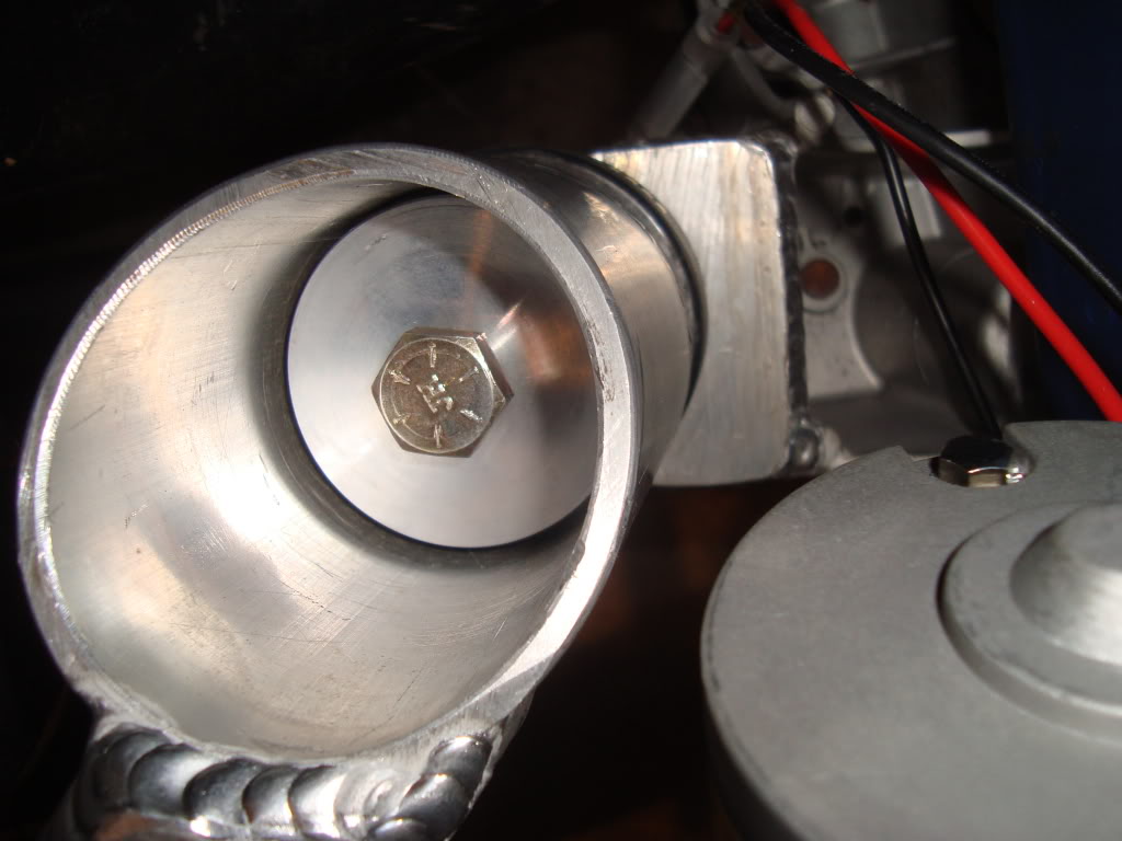
All stainless bolts were used on the mount plate and power steering pump front and rear. The alternator
stainless bolts still need to be sourced.
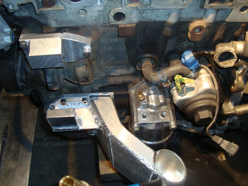
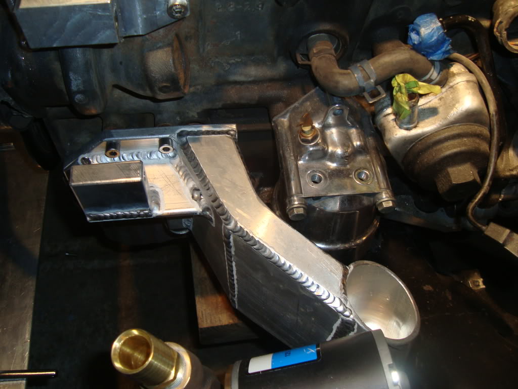
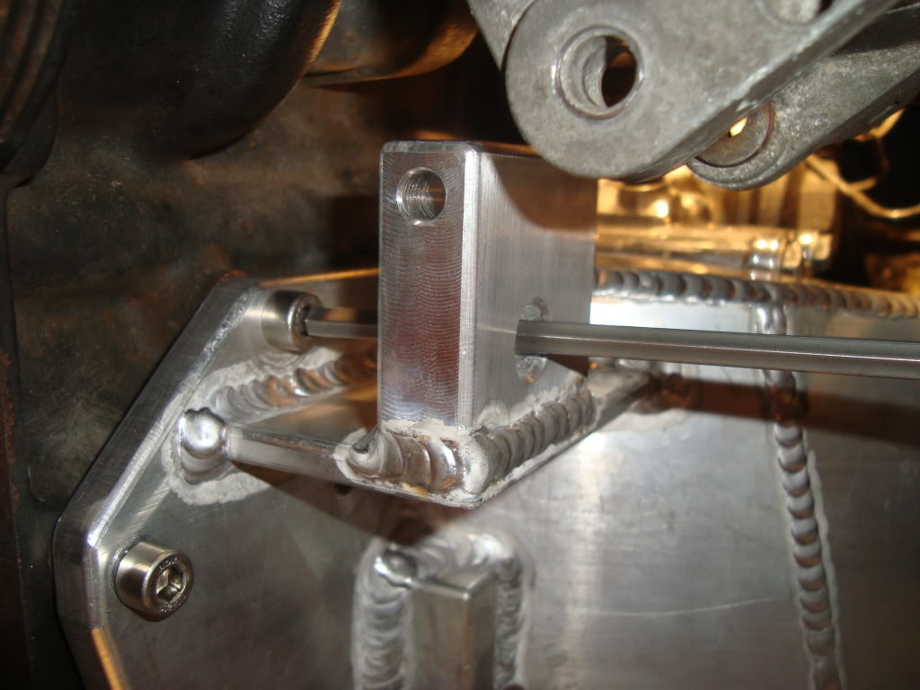
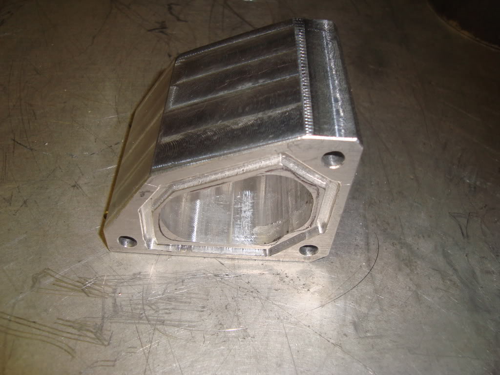
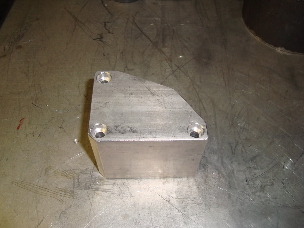
This is the base for the passenger side mount. Fab work should begin in the next couple of days.
will switch solely on the cooling system until that’s complete. The alternator and power steering pump will be rebuilt or replaced
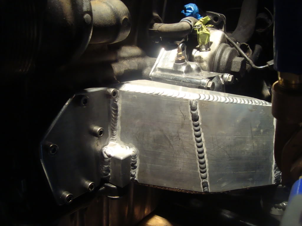
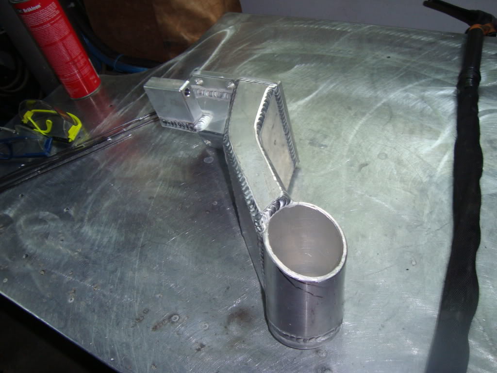
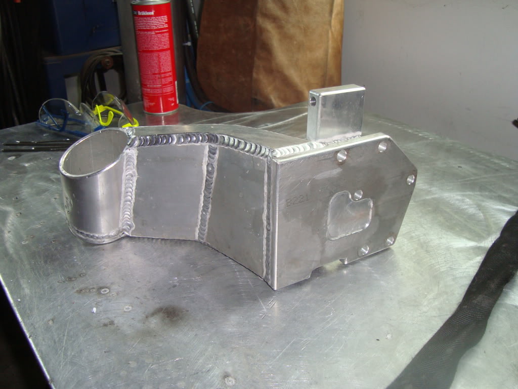
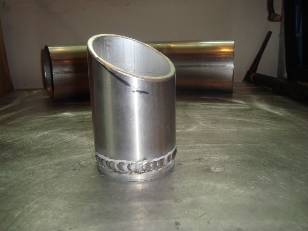
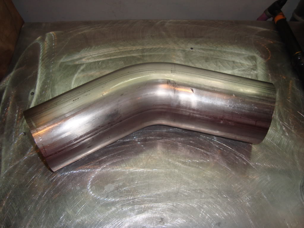
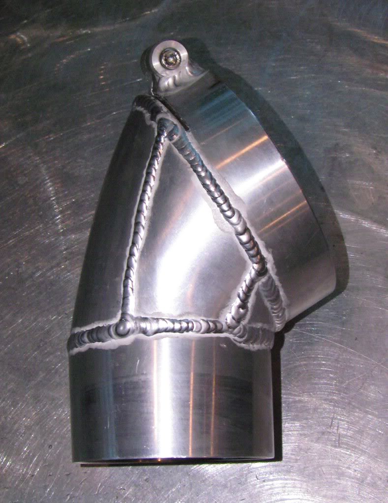
with new units.The exhaust fab will begin after the engine mounts are finished.This is the elbow for the 4″ downpipe.
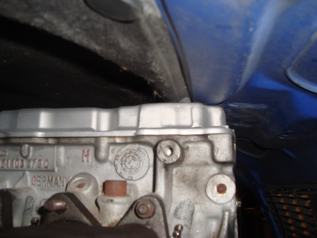
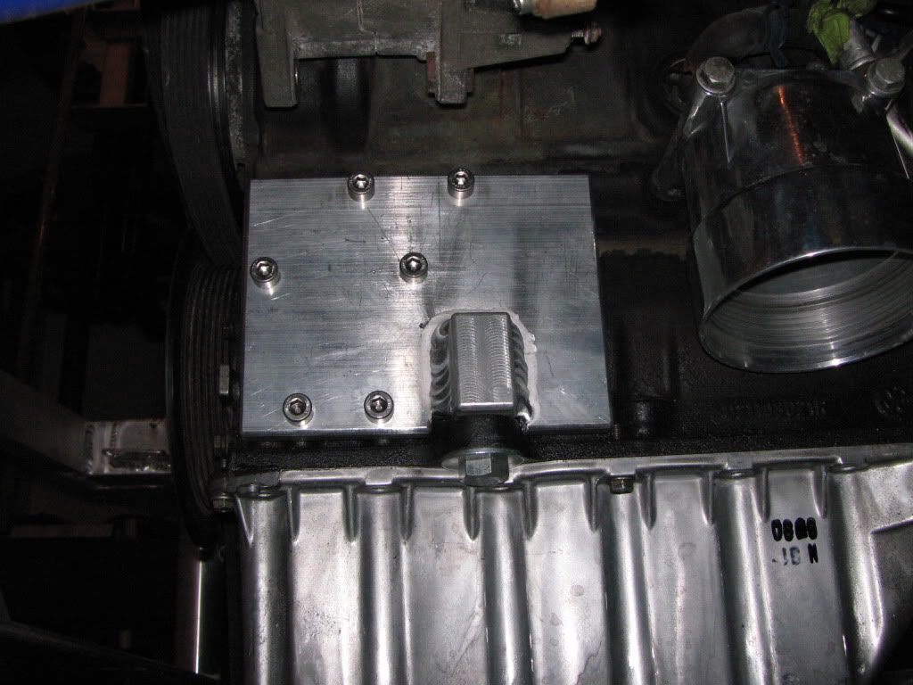
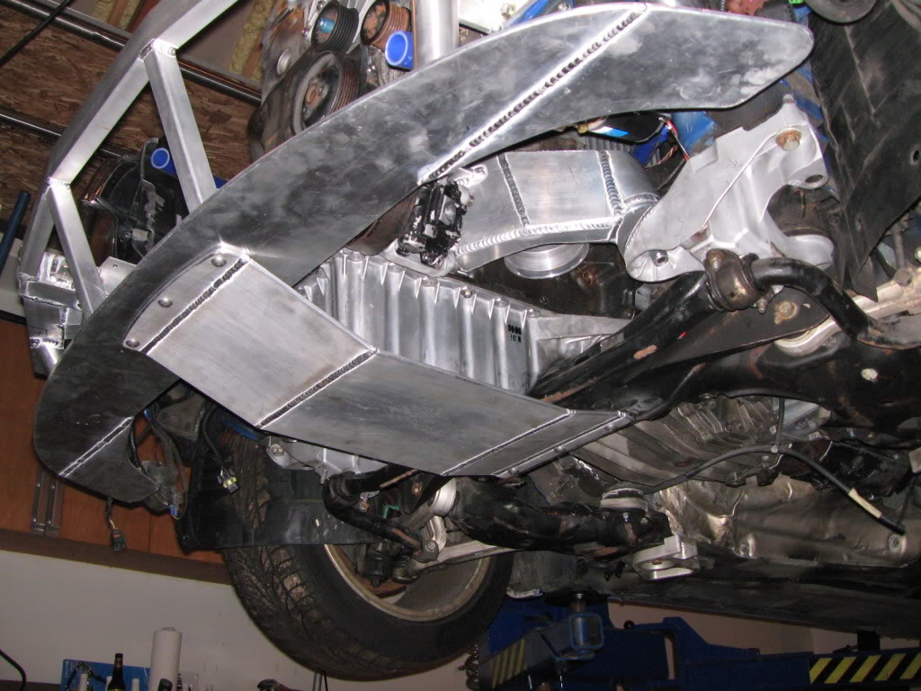
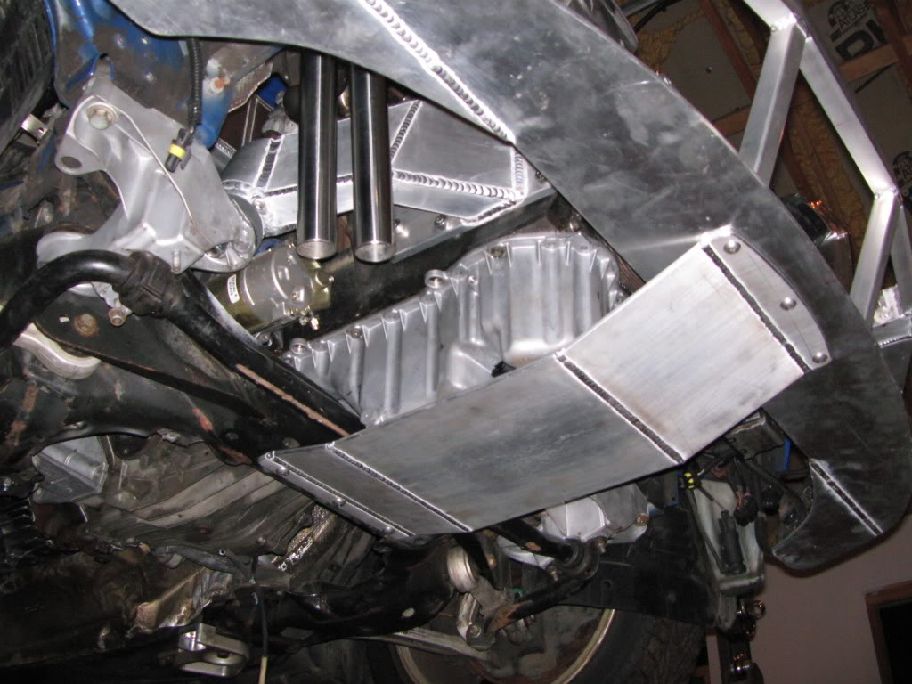
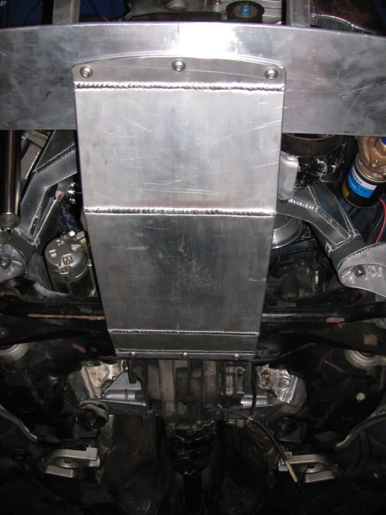
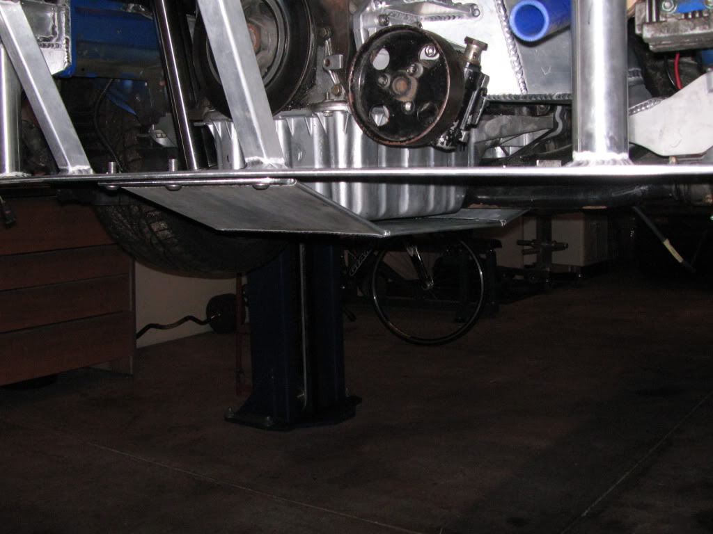
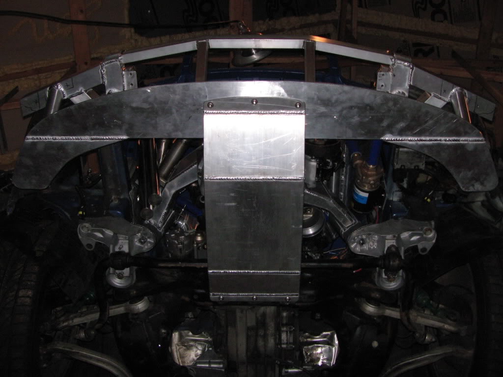
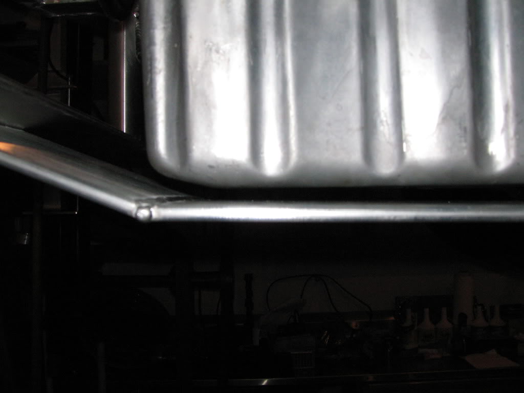
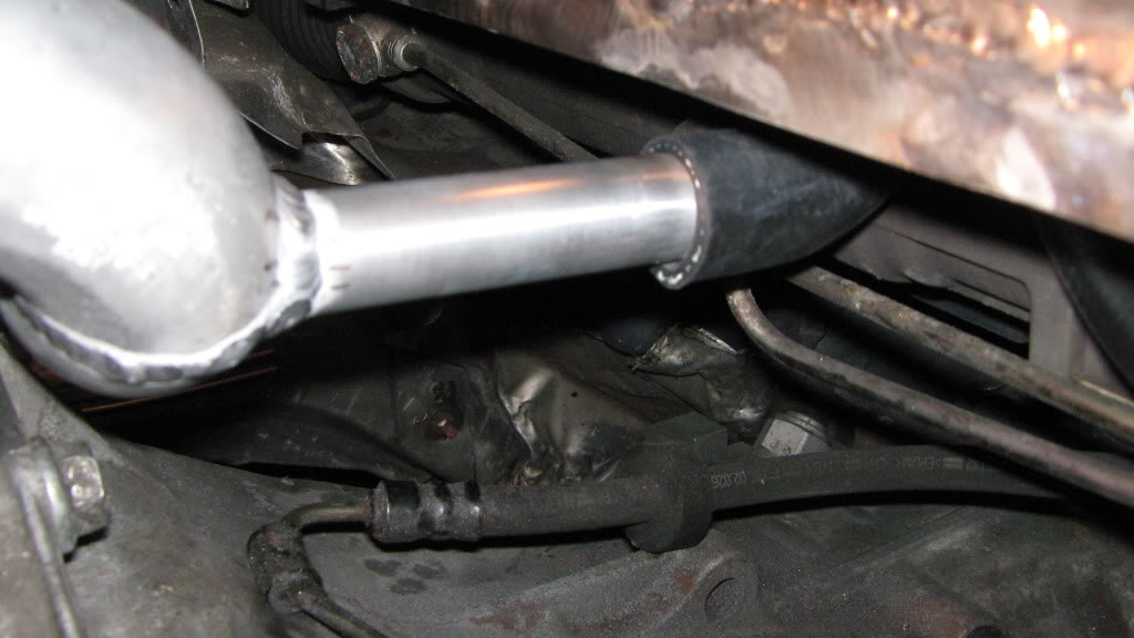
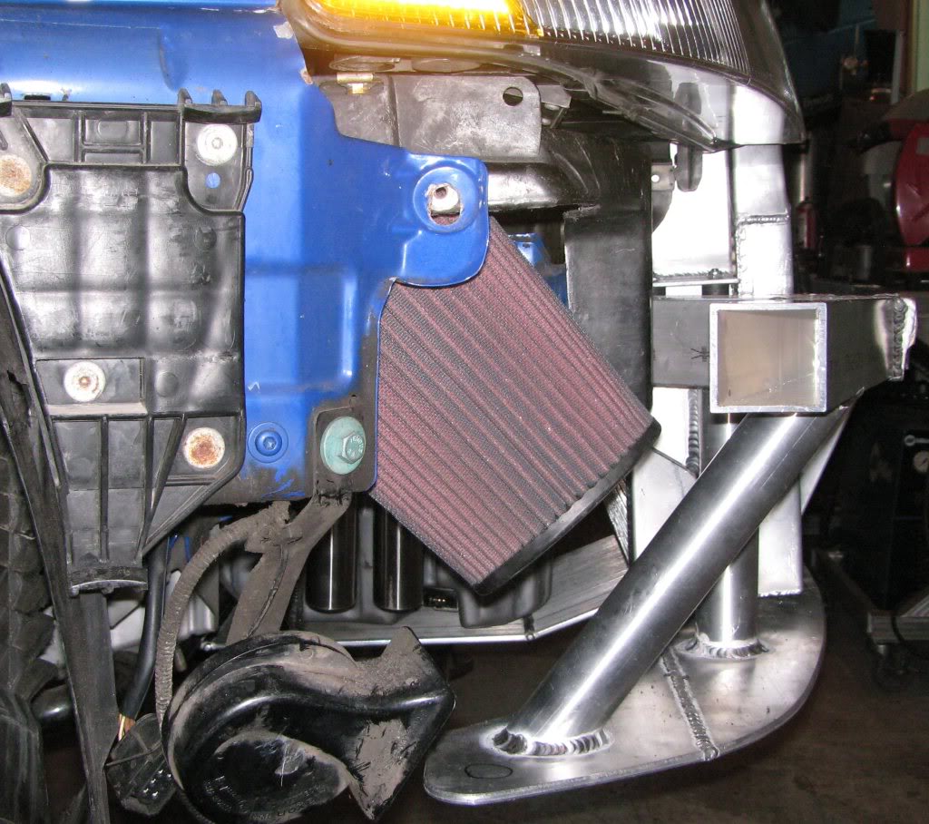
Here’s the underboob shot!
that was the cause of this project, a pothole! I don’t know the origination of the oilpan, and I waited over three weeks
for this one, so anything that can protect it is a great benefit. Anything that can be done to reduce downtime is also a plus!
I am getting the full set of Gruven pulleys now just because…….
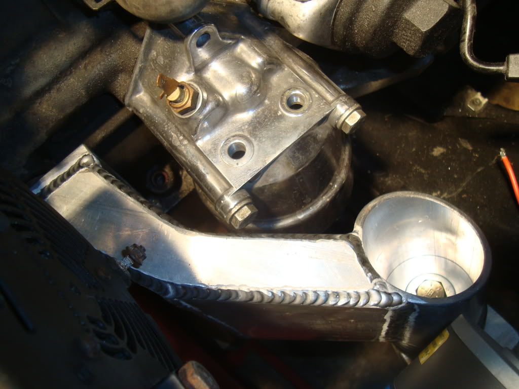
perfectly gasket matched.
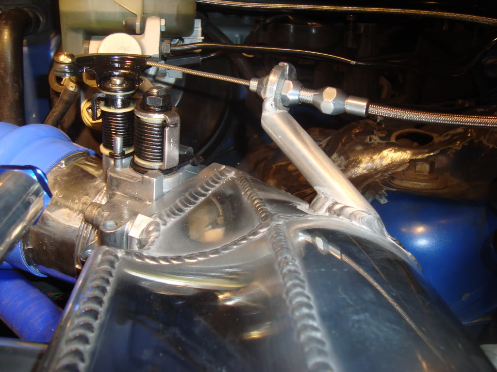
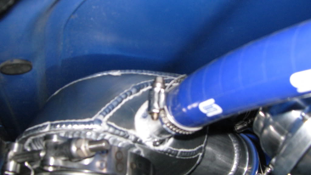
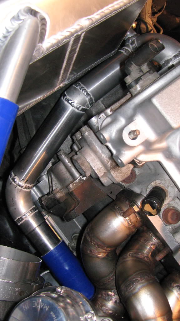
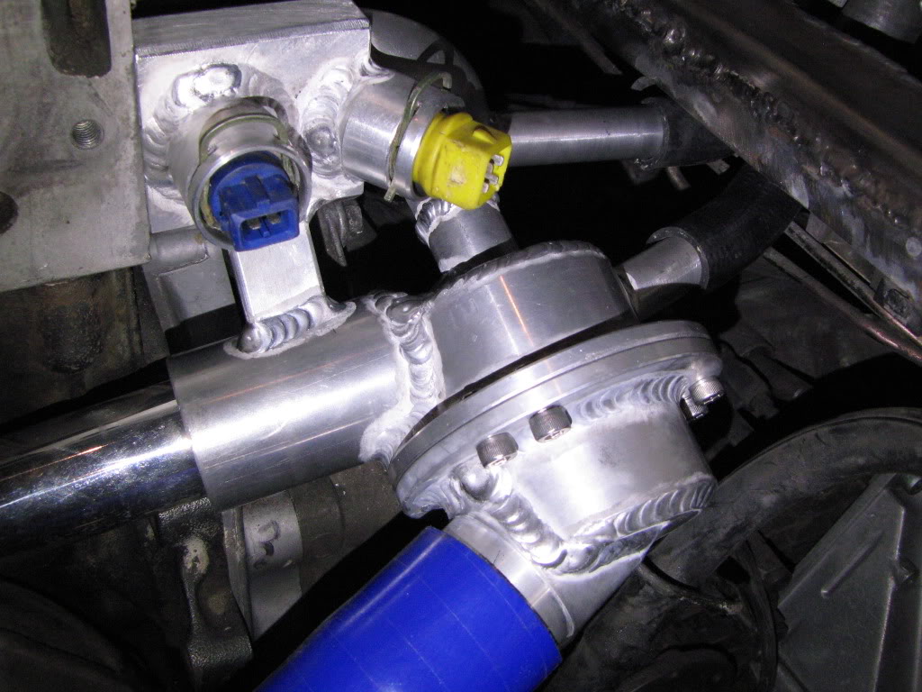
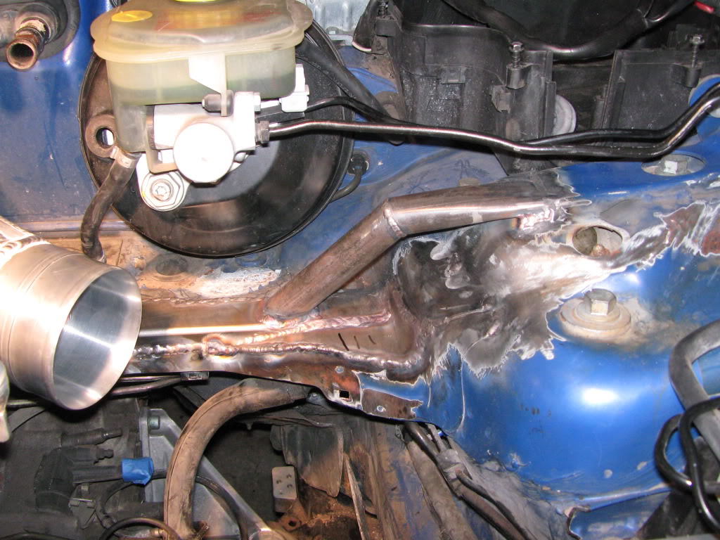
The water pipe is angled down to clear the 4″ downpipe.
This aluminum spigot feeds the interior heater core.
The silicone hose will need to wrapped to protect it from the radiant heat of the turbo manifold.
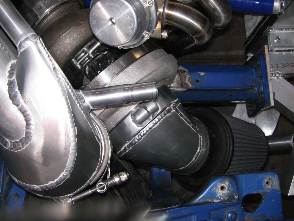
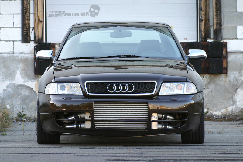
WAAAAYYYYY back when this project first started, this was all I envisioned…..a clone ATP manifold and a GT4094R with an aluminum intake box welded to the stock VR flange. Also, I planned to use the 034 engine cradle, a head spacer on the stock block with only 25psi max along with the 034 Stage IIC standalone. I figured about 600 crank HP at best.
It’s funny how things change so quickly! The question that started this build was “What do you REALLY want to do?” Well, you see it right before your eyes! This is the stuff dreams are made of! I can’t wait until I can drive it and experience what it feels like.
I will say this, Jon skills are absolutely ridiculous! I find myself just staring at the car thinking the whole time to myself “Damn, this is nuts!” I took a few of my friends to see the car and their mouths just dropped. It looks way better in person. My friends are now even more hyped than I am, and that’s hard to beat. Damn, I can’t wait!!!

Everyone is telling me that if this car doesn’t produce the times I’m shooting for, the car needs a driver mod. LOL. We’ll see…..
More updates are coming soon!
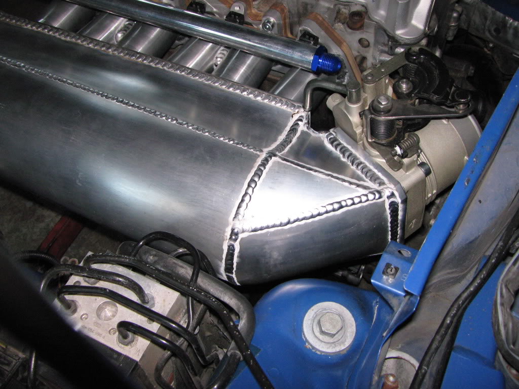
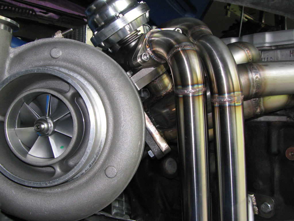
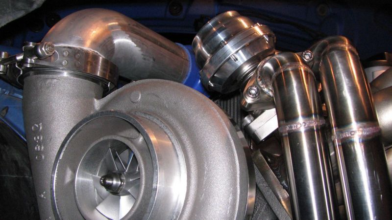
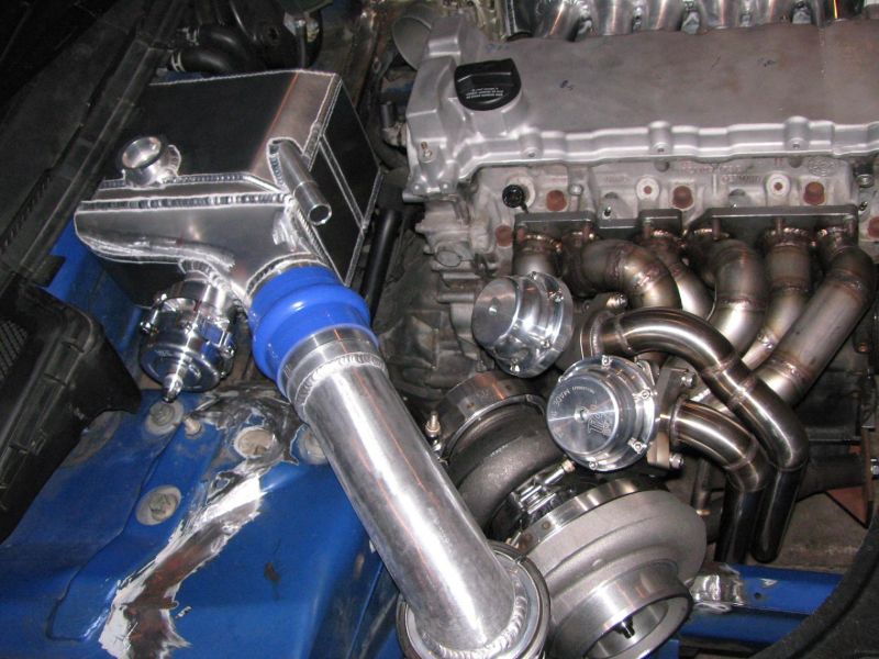
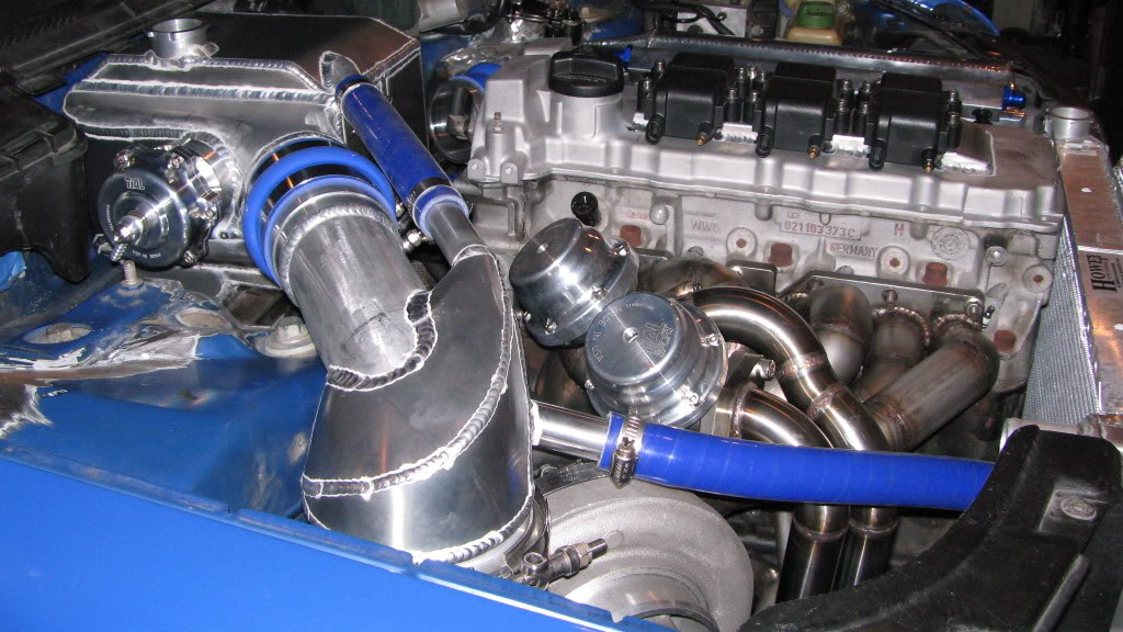
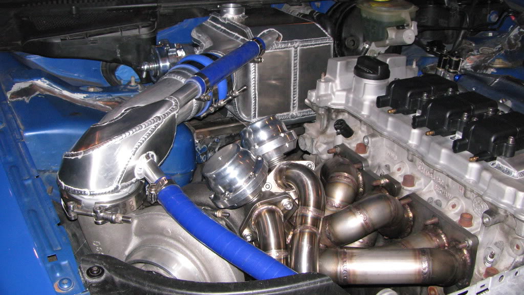
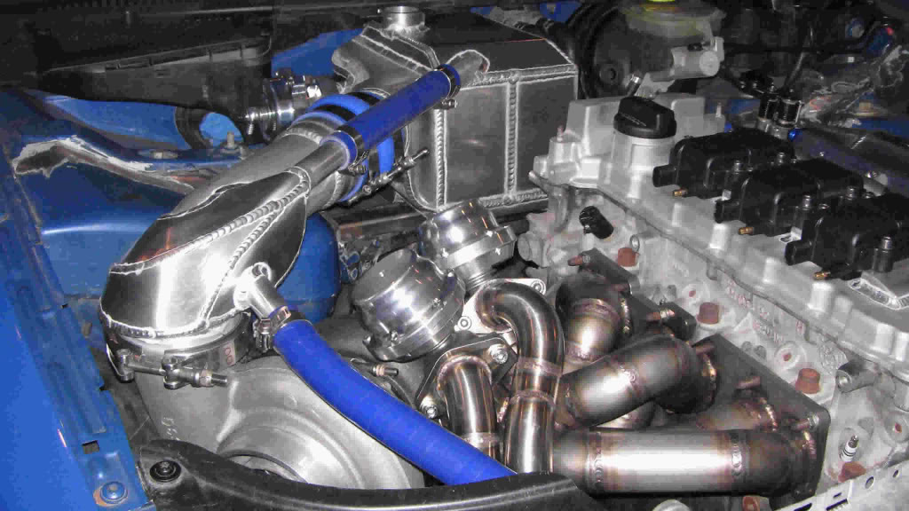
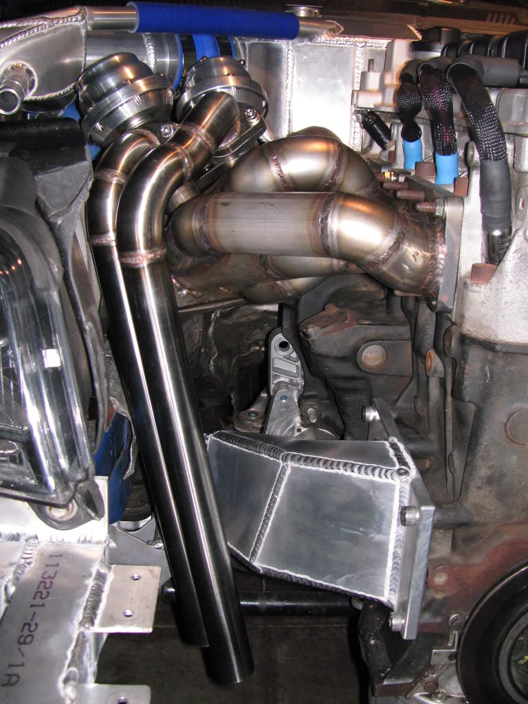
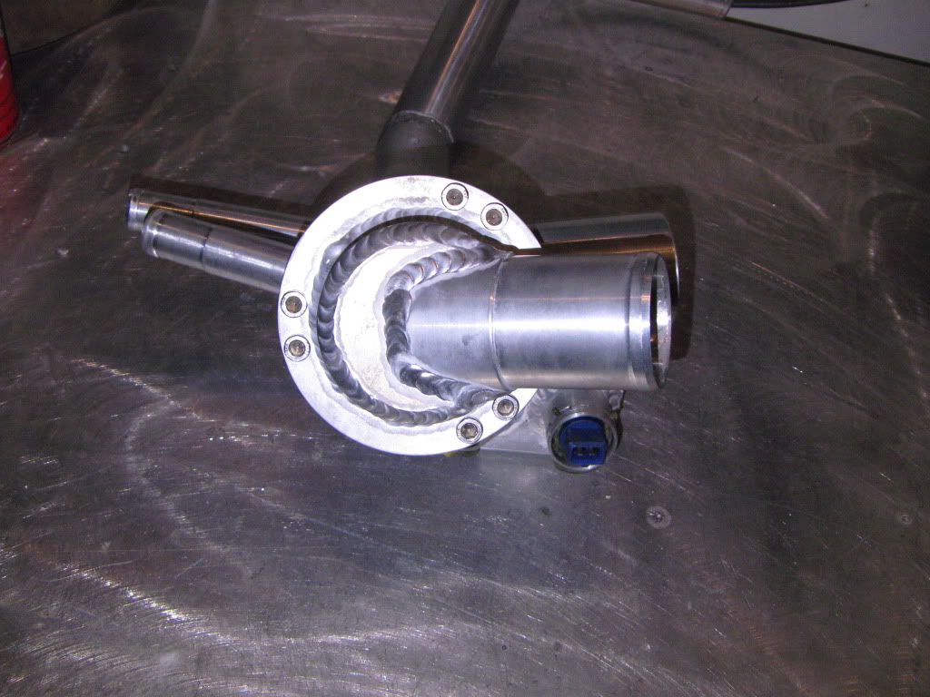
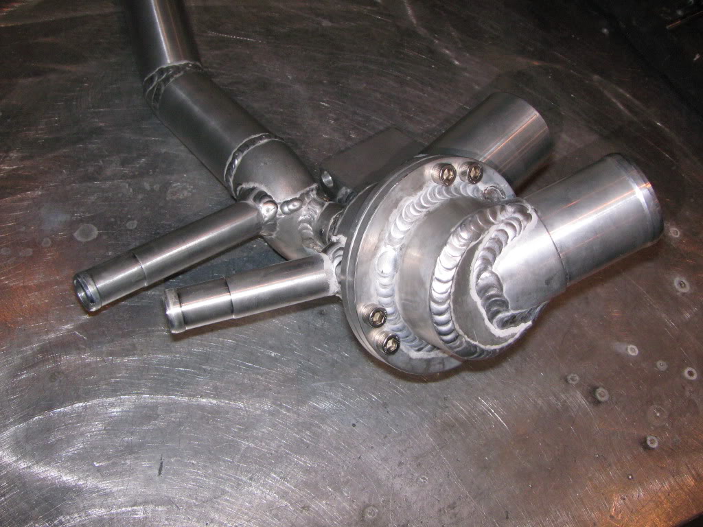
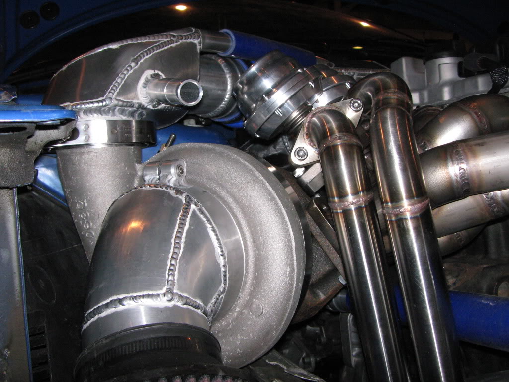
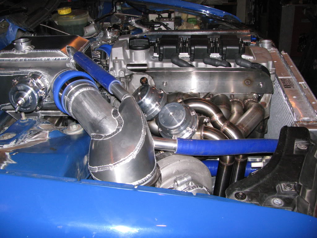
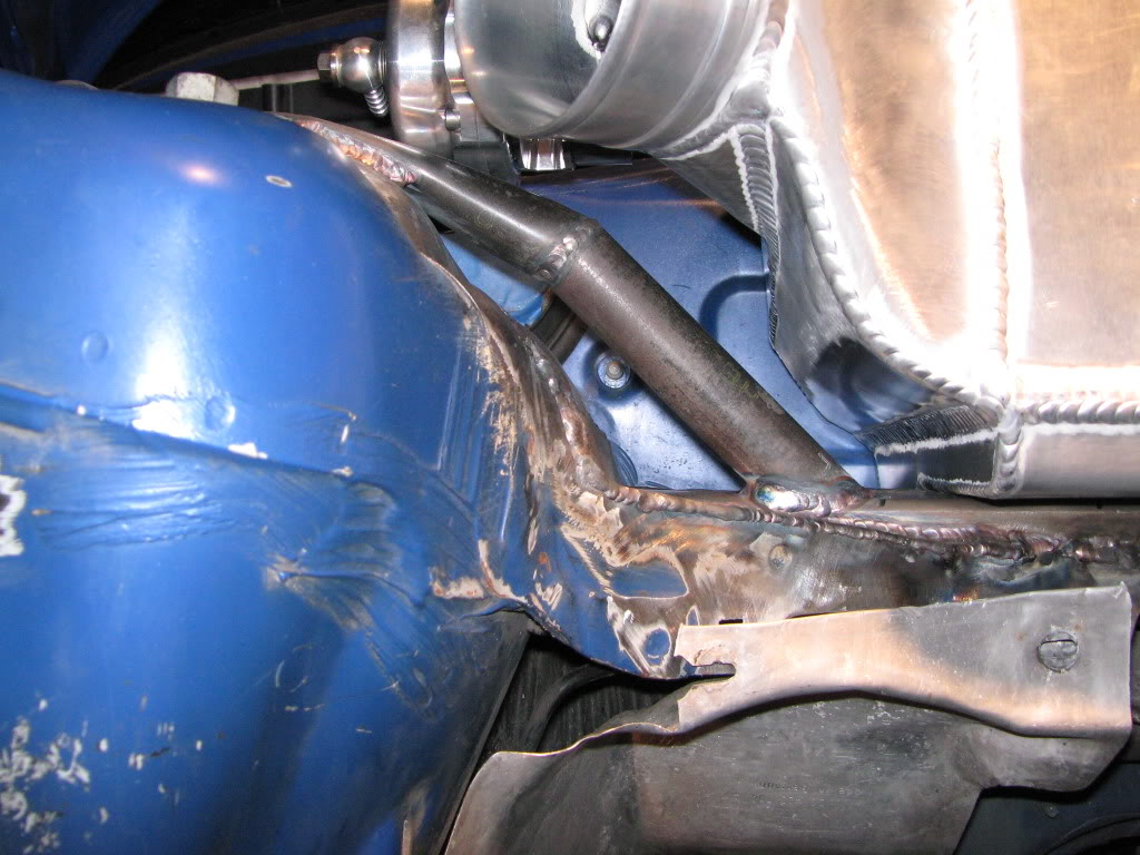
The turbo is a twin scroll unit and the manifold is divided into 1-3 and 4-6 to utilize the design. Each scroll has it’s own independent wastegate and 3 tubes feeding each one.
-
Here is a good pic showing the design

-
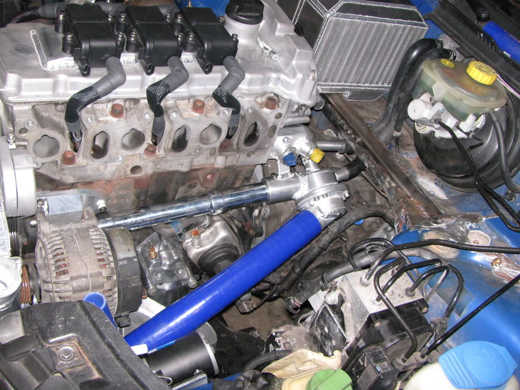
UPDATE! The thermostat housing and coolant system is complete!!
-
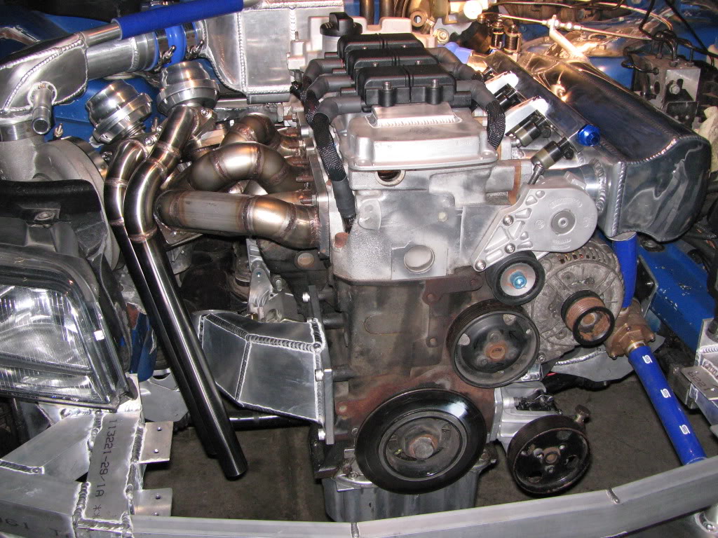
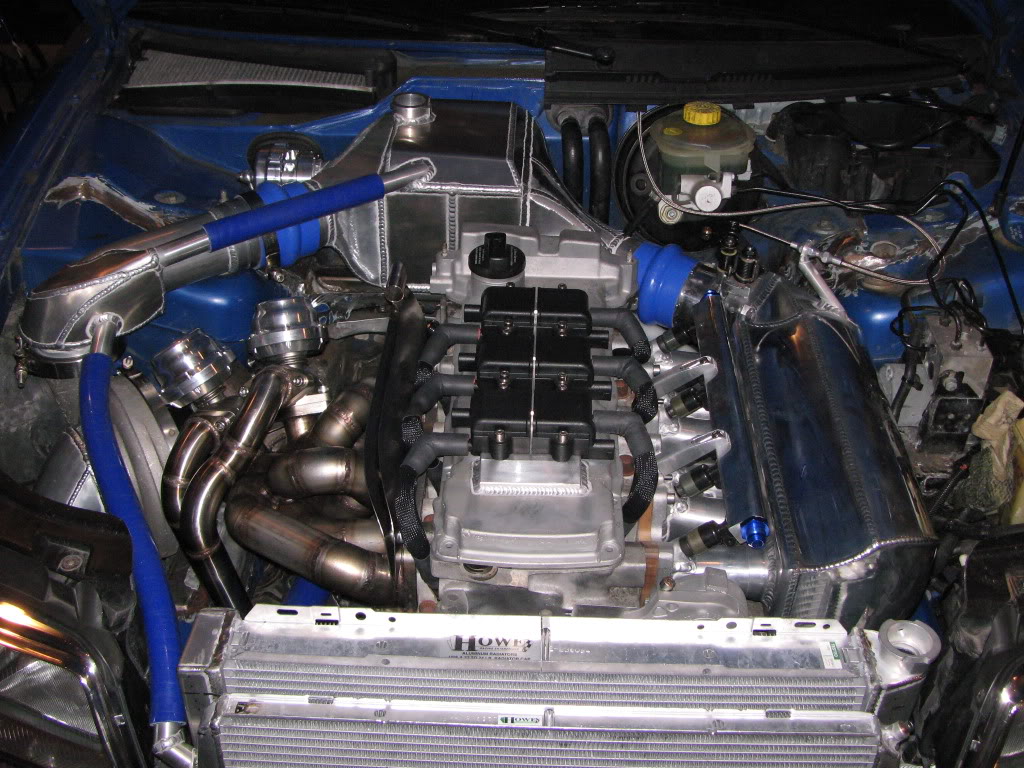
Here’s what it looks like to date…………..
This is the updated “TO DO” list.
1. Alternator bracket – Done
2. New engine mounts – Done
3. Thermostat housing/coolant system – Done
4. Catch can
5. Exhaust with cut out – In process
6. Skid plate – Done
7. Splitter
8. Longblock assembly – In process
9. Wire the standalone
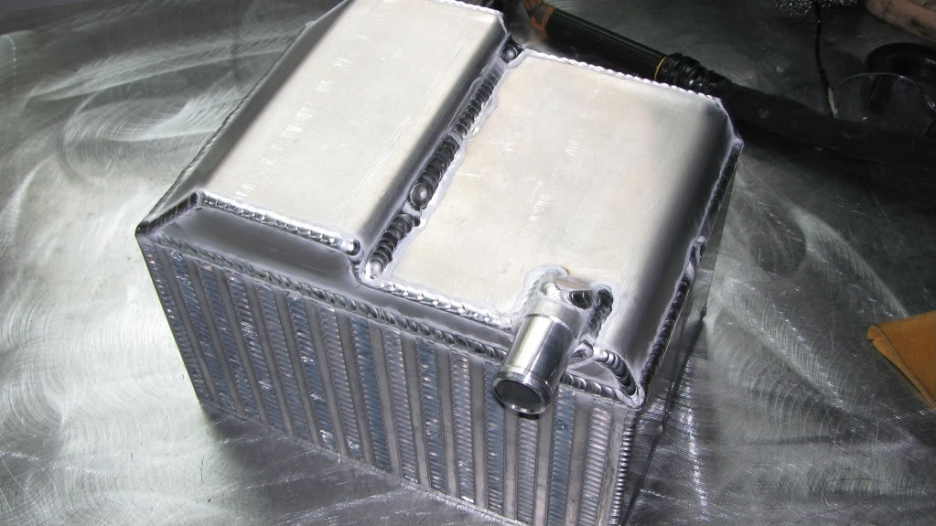
10. Finish the intercooler end tank – Done
11. Install the fueling system
12. Make more mounting provisions from block to adapter to trans
13. Tune for pump and race gas
14. Smooth out engine bay and paint
15. Hide receipts from wife and enjoy life!! – Ongoing battle
-
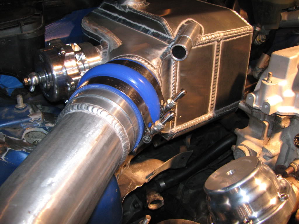
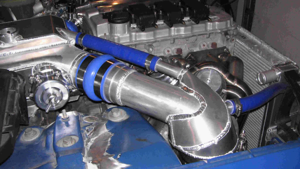
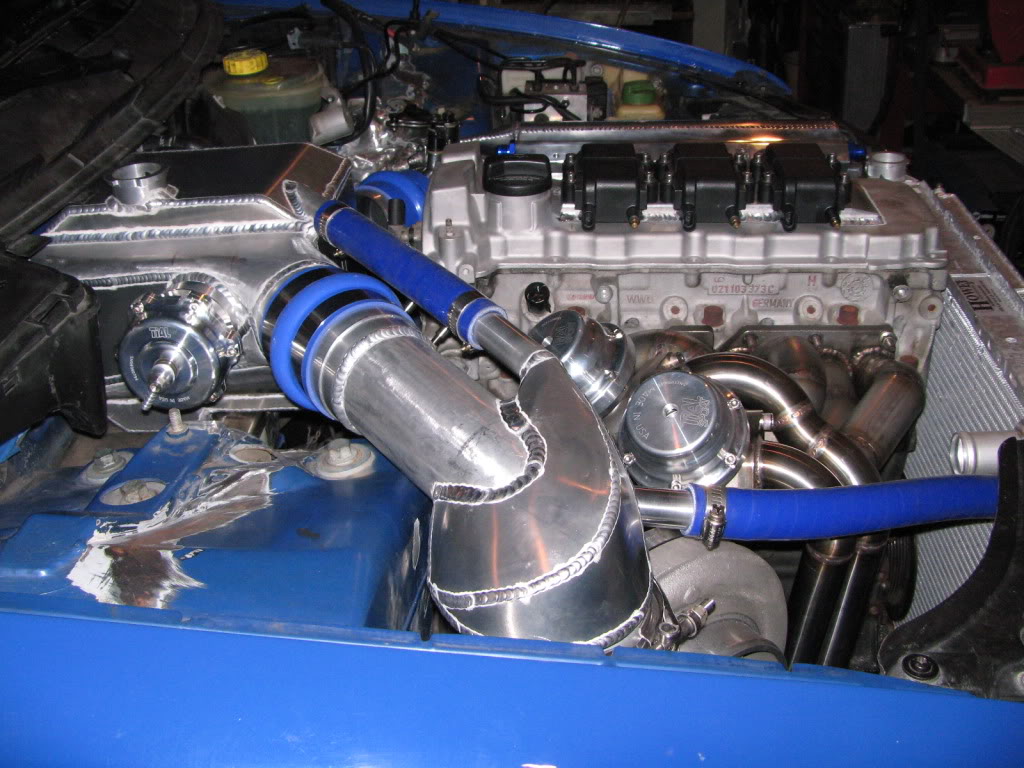
UPDATE! Problem. I couldn’t find a tight radius 90 degree 5″ to 4″ reducer silicone hose for the turbo inlet.
Solution. Jon made one out of aluminum!
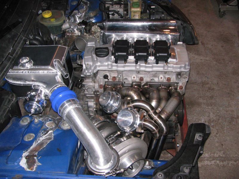
The turbo inlet pipe is complete!
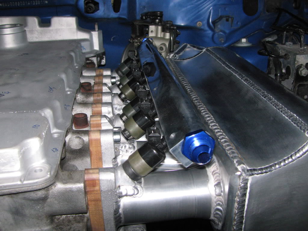
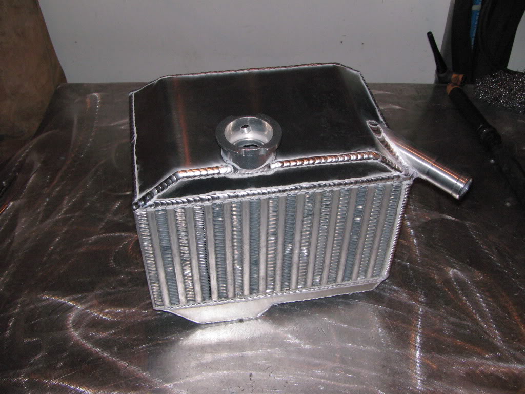
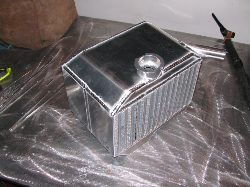
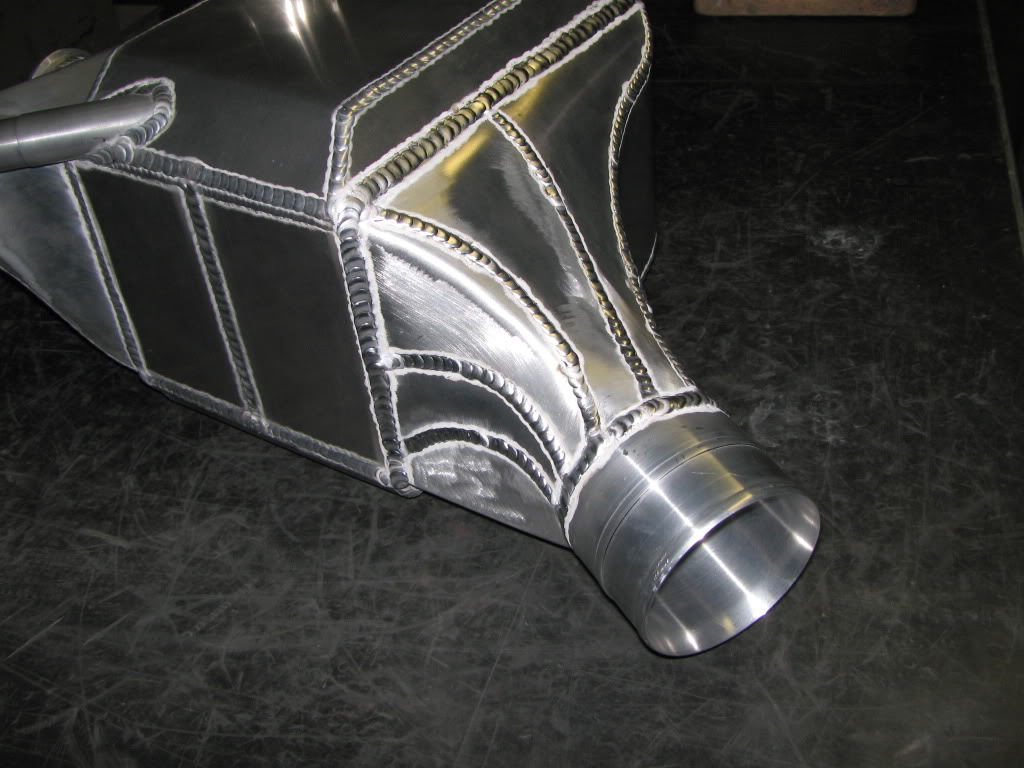
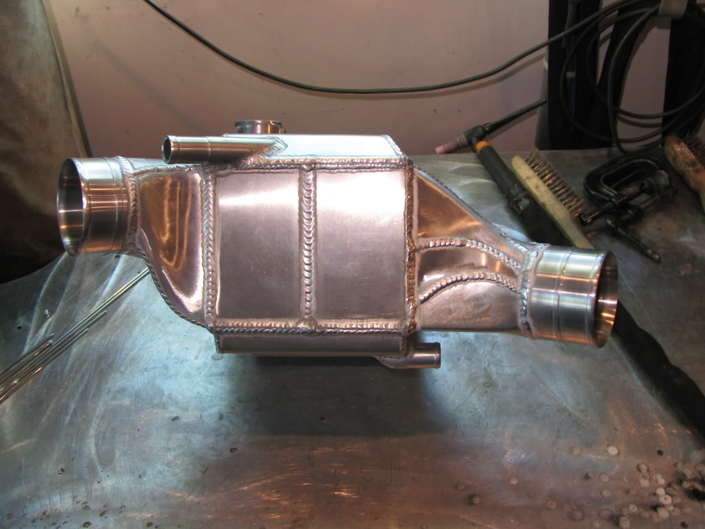
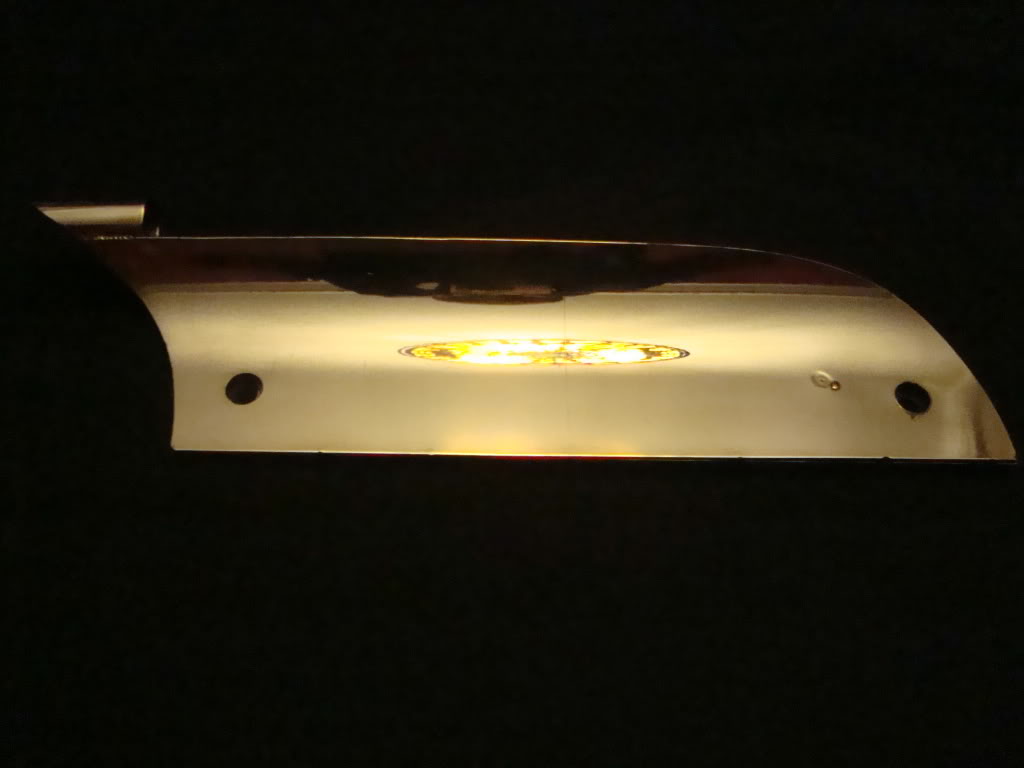
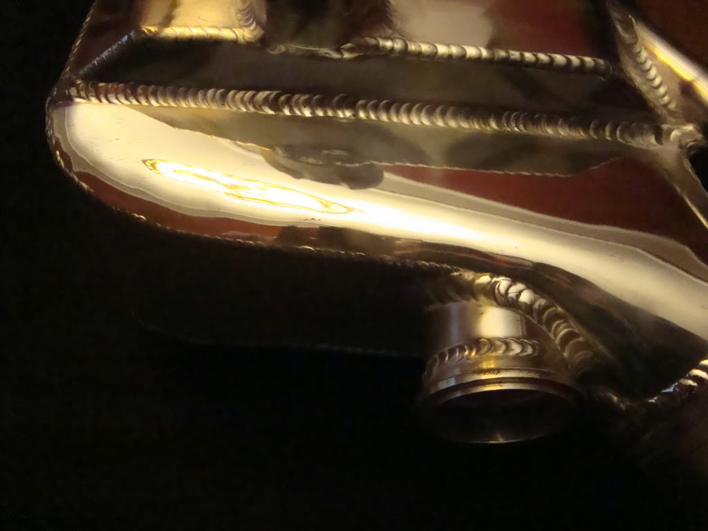
UPDATE!! The air to water intercooler is finished!!
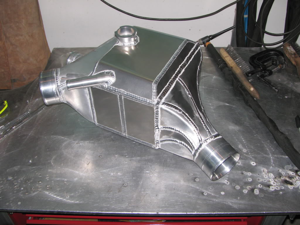
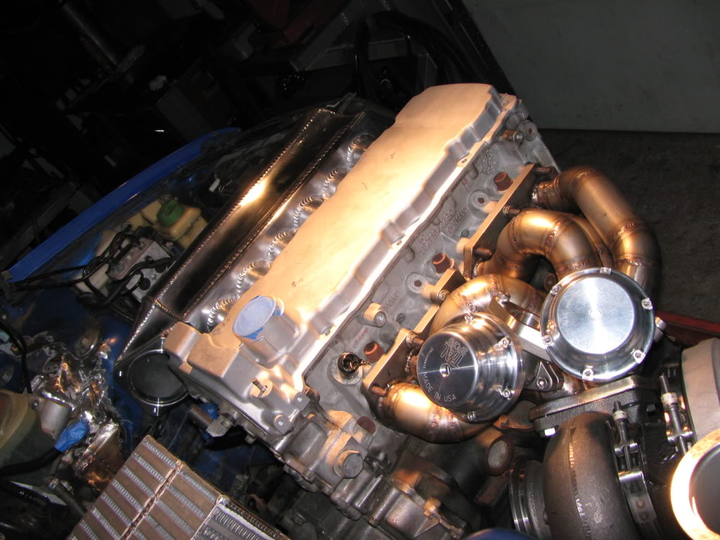
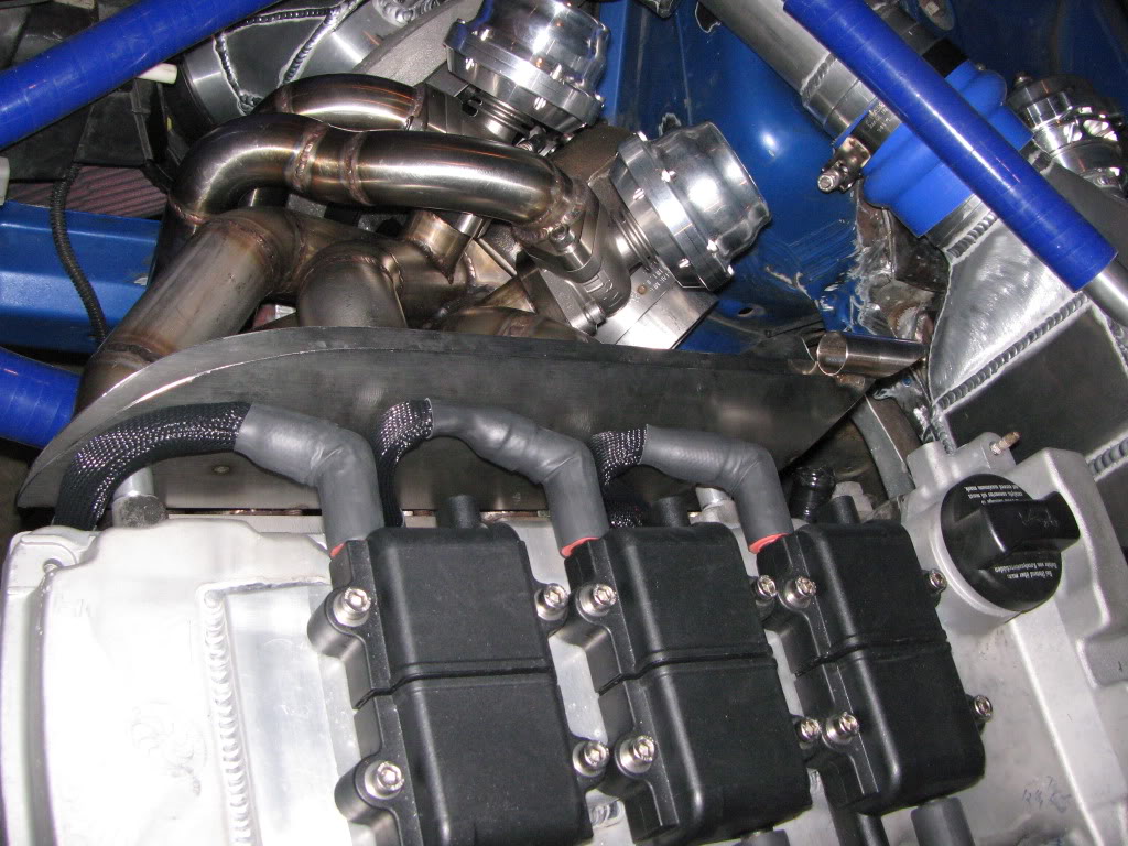
A stainless heatshield was made to protect the spark plug
| Click this bar to view the full image. |
| Click this bar to view the full image. |
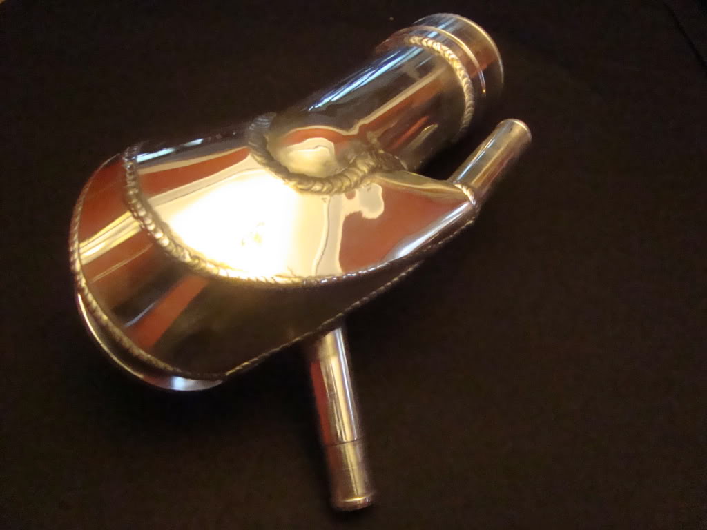
After looking at it for awhile, I wondered how it would it look polished. Hm-m-m?
| Click this bar to view the full image. |
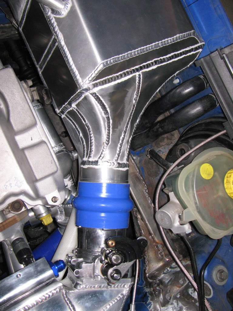
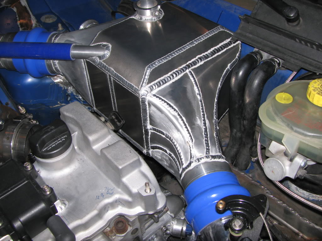
Then impulsively I thought about the intercooler…………….
| Click this bar to view the full image. |
Then I got a little too excited………..
| Click this bar to view the full image. |
Now I gotta polish ALL of the aluminum parts. Damn.
Getting back to the S4…..
More bracing was added because the original stress bar was removed and a stainless 1.5″ X 1″ bar took its place.Jon tied in the original location back to the stainless bar.
Now the car is at the paint shop with the interior completely stripped except for the dash and steering wheel. I’ll update on the body work once it starts.
Right back where I started months ago……
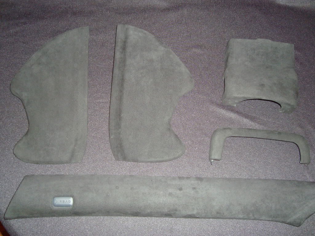
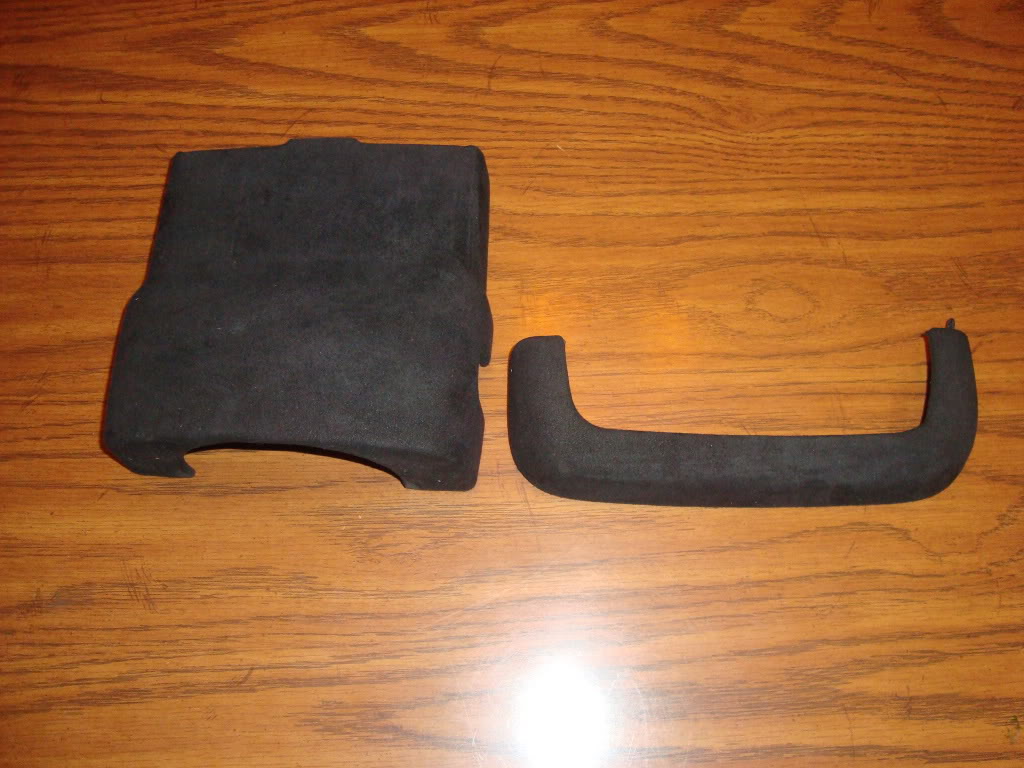
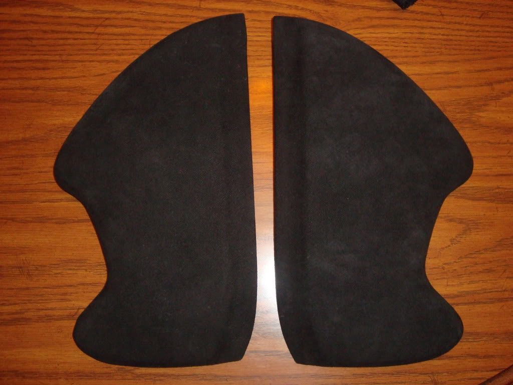
The A pillars, the side panels for the dash, the upper steering column by the cluster, and the lower steering column cover are done. I’m still working on the upper cover.
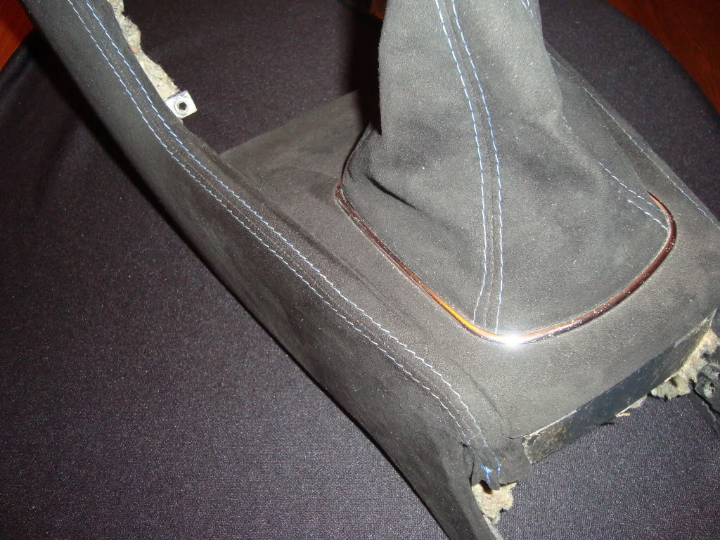
Andy at Project Two Customs made the patterns and sewed up the center console for me.
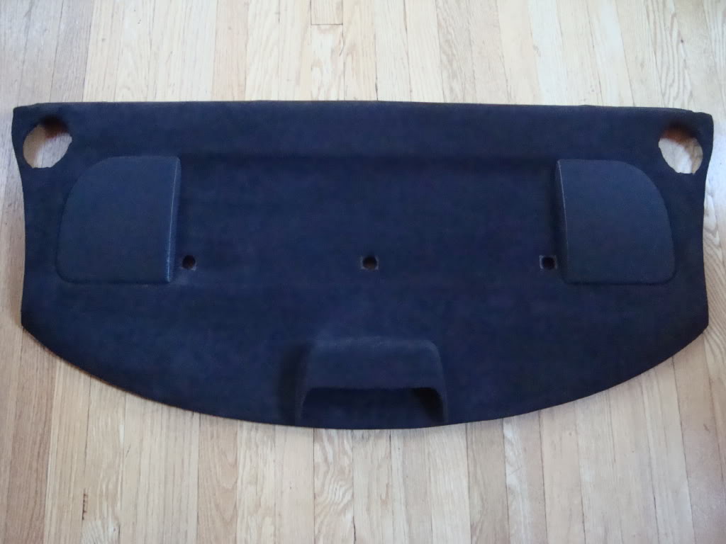
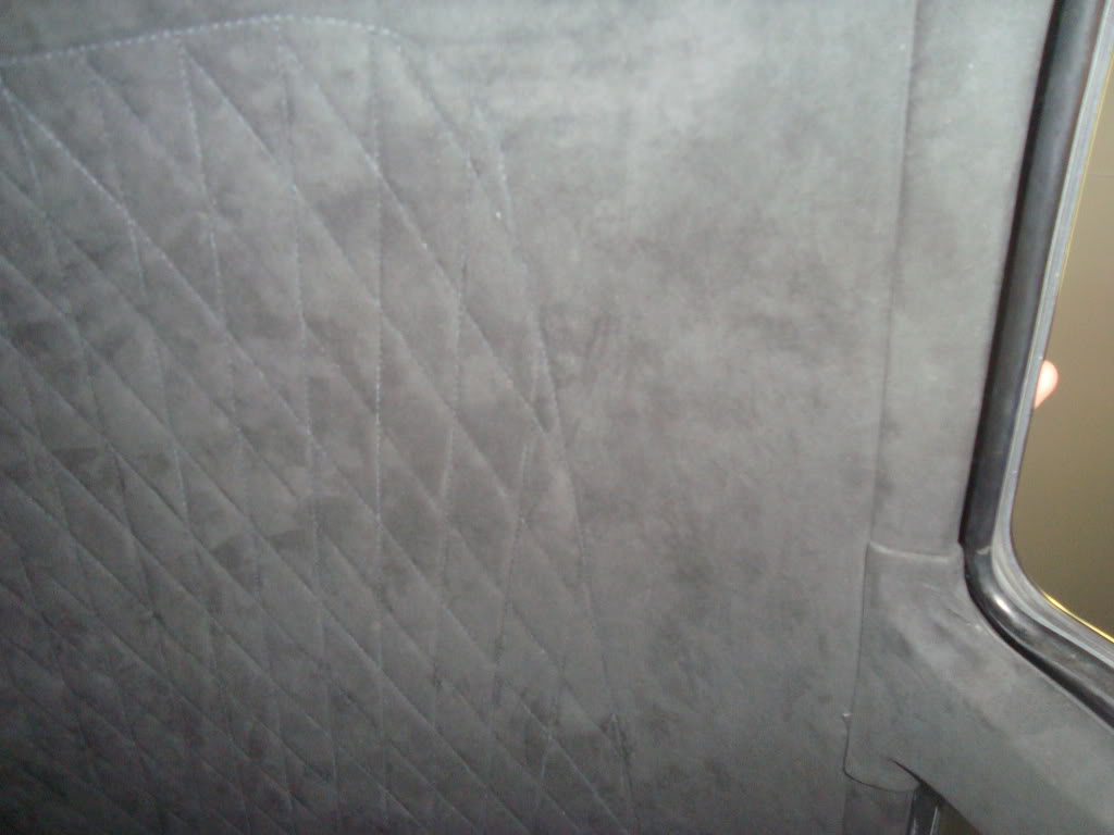
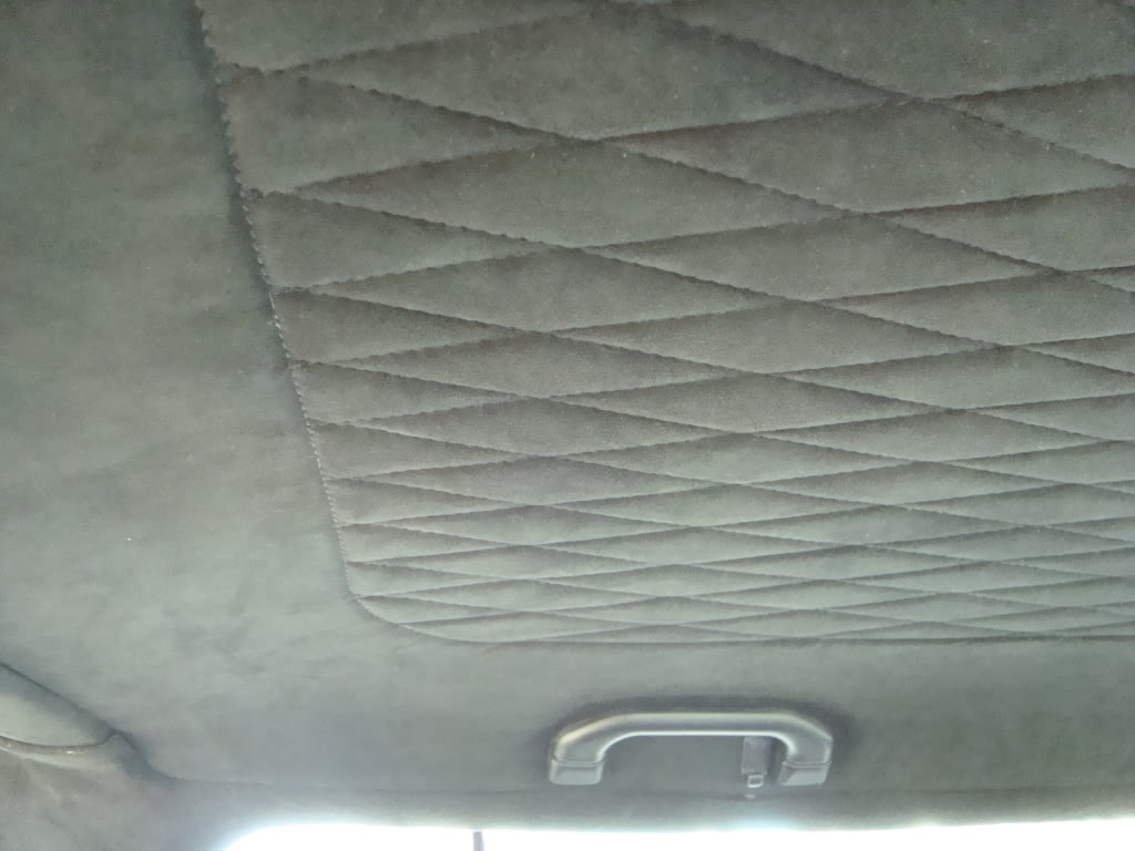
The glove box is almost done and the knee bolster is already wrapped. The headliner is finished too, but I’m picking up another
one to do something similiar like I did in my Jetta.


you are amazing. I wish to hear it running, do you have any links?
thank you